

The 7800 Mod Mess Mixup Fixup - pt. 3
Entry posted by Nathan Strum in 7800 repair
553 views
When we last left the 7800 Mod Mess Mixup Fixup™, alex_79 helpfully suggested:
On 12/23/2022 at 1:12 AM, alex_79 said:That's weird. Seems like the "two buttons" joystick functionality for the left controller is enabled in 2600 mode, which shouldn't be possible normally.
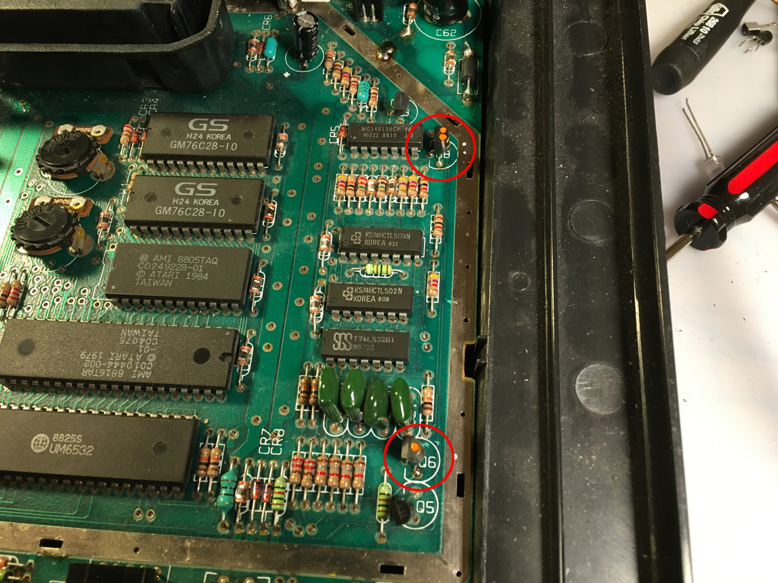
Two button mode is achieved by strongly pulling up pin 6 of the joystick port. To do that, for the left port, both the TIAEN signal (green) and pin 22 of the RIOT (PB2, blue) need to be LOW, to switch on the two transistors (red and yellow).
I'd check if those two transistors are good, and if there is any short in the areas near to those components before trying to replace the RIOT.
We'll get back to the transistors in a minute. Meanwhile, I decided to rip out the HDMI "mod" as a first step, because: 1) It's horrible, and 2) I did find a short between ground and the composite video output that I traced back to that mess. I didn't take pics of the process, suffice to say it involved cutting wires, desoldering and re-soldering, chewing through a glued-down HDMI connector with side-cutters, and lots and lots of prying to remove epoxied-on crapola. Here's the debris field:
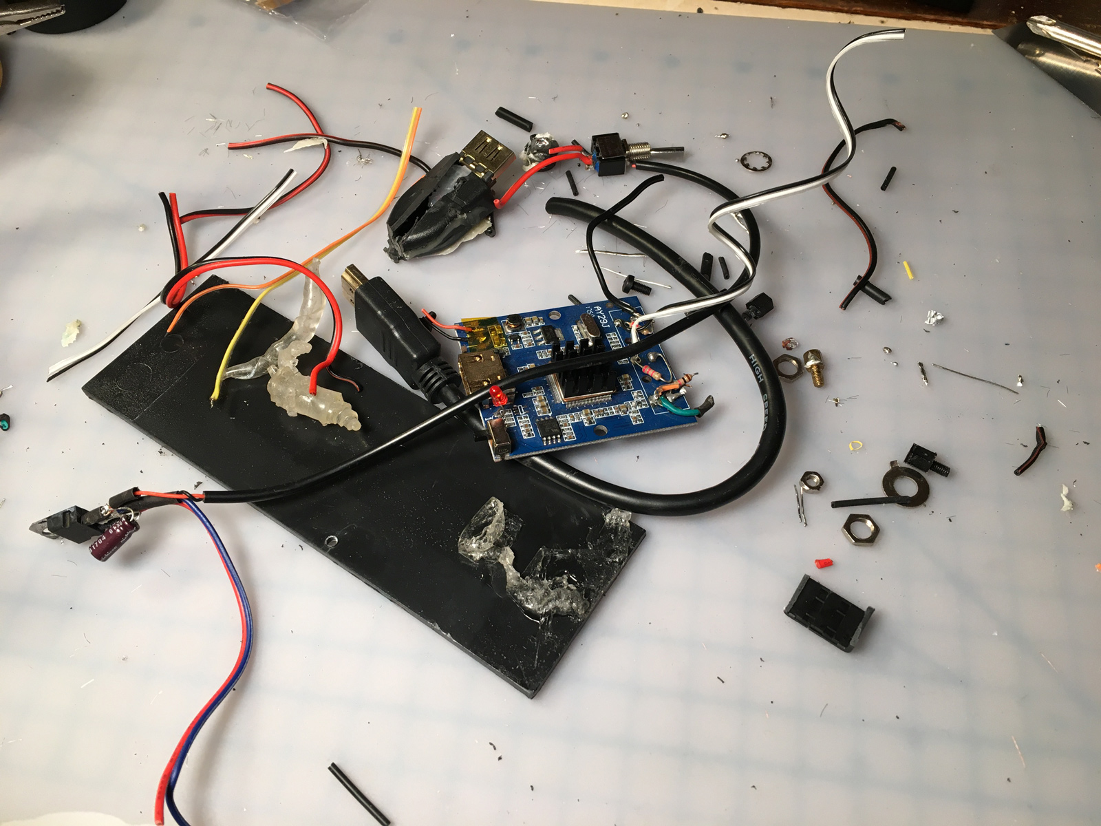
Good riddance to bad rubbish!
The "mod" was stuck down to the RF shield with some sort of clear, sticky goop. Still haven't cleaned it all off yet. They also soldered ground wires to at least four places on the RF shield. For some reason. Still have to de-glob those as well.
All of the prying resulted in some minor denting. I'll try to smooth them back out before final reassembly. And maybe try to remove those fingerprints.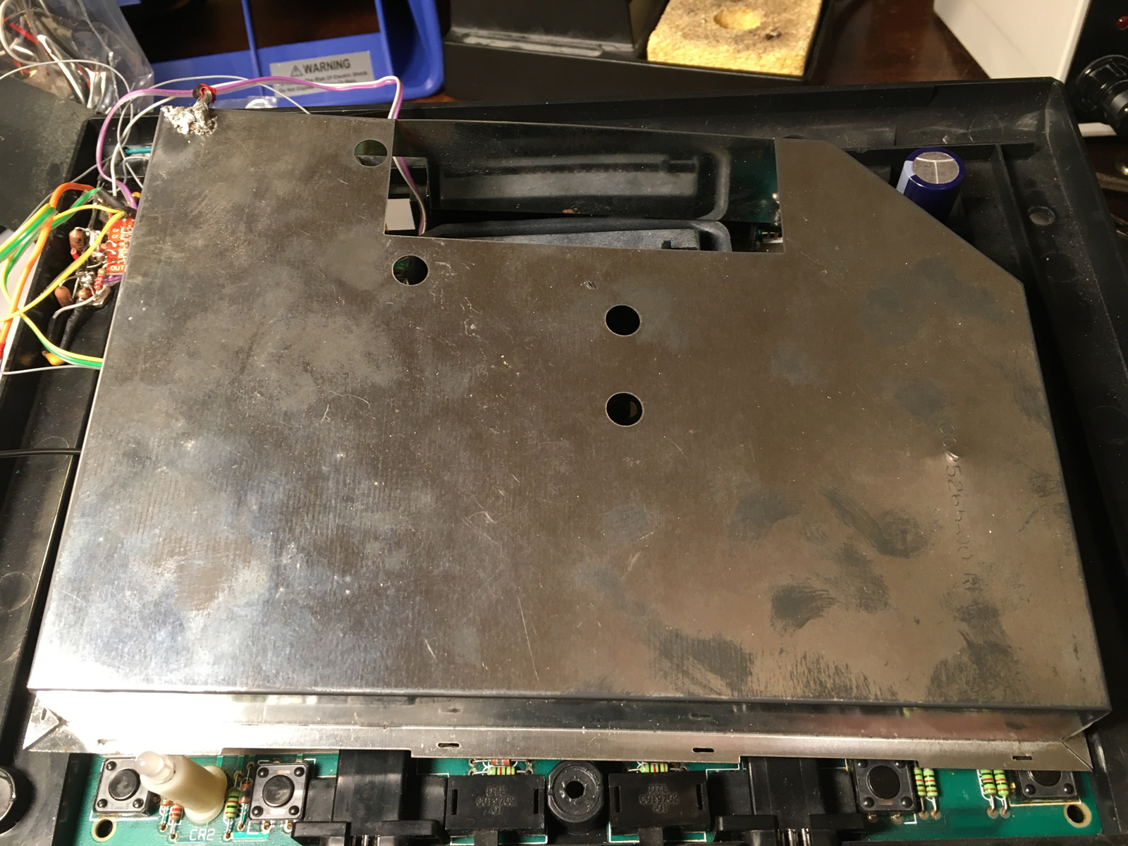
They'd replaced the stock 2200µF cap with a big, honkin' 4700µF one. They'd also screwed a second voltage regulator to the RF shield to supply power to the HDMI "mod".
I reconnected the basic composite + audio mod, just enough to make sure the 7800 still worked (to the degree that it did before).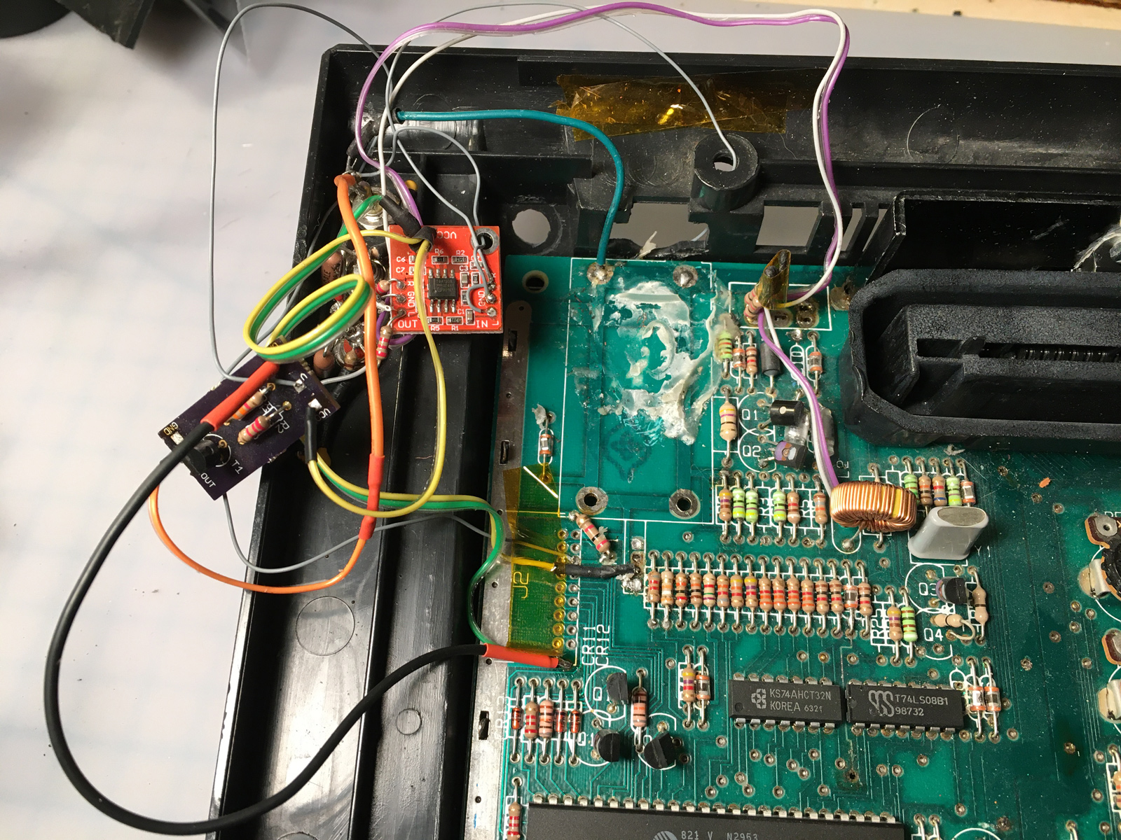
Here's the bottom of the 7800, where they attached the TIA audio: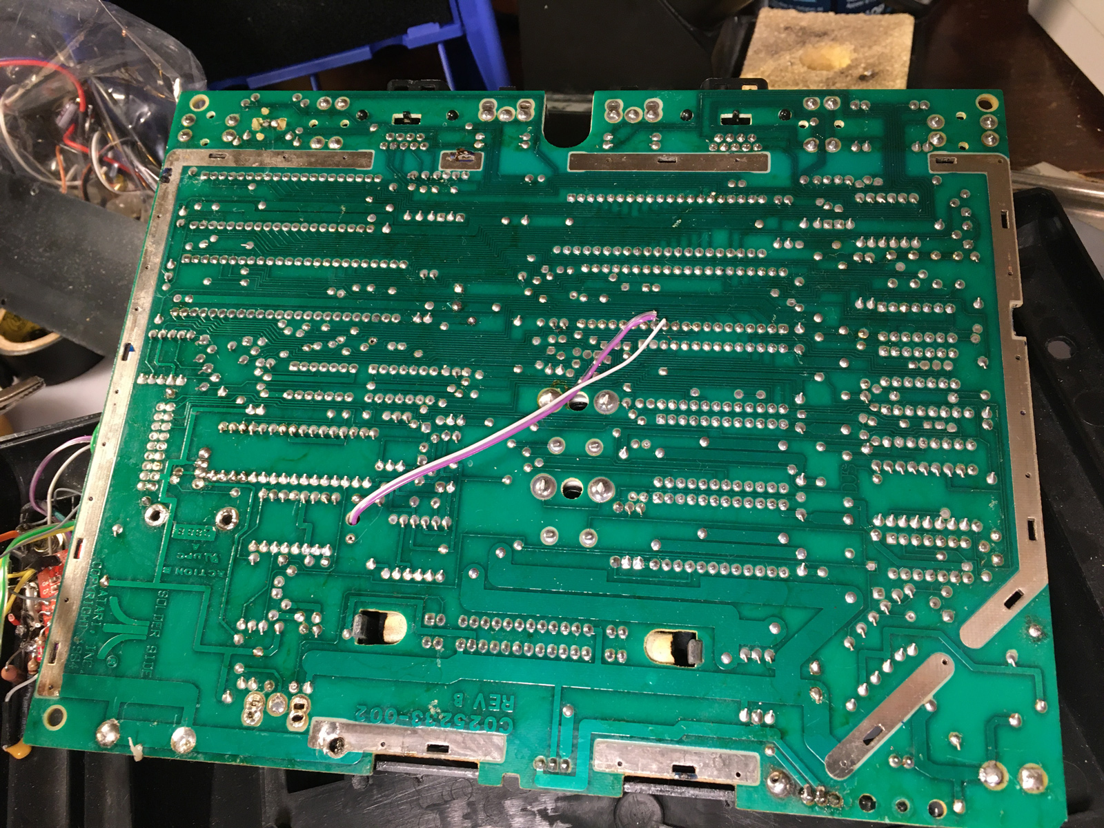
I still need to clean off the snot (or whatever) they used to glue down the HDMI cable. There are also a few components they removed when they ripped out the RF module. Jesse (aka -^CrossBow^-) has been kindly answering a bunch of my questions and made some helpful suggestions about what needs to go back and what doesn't, in preparation for the UAV mod that will be going in there.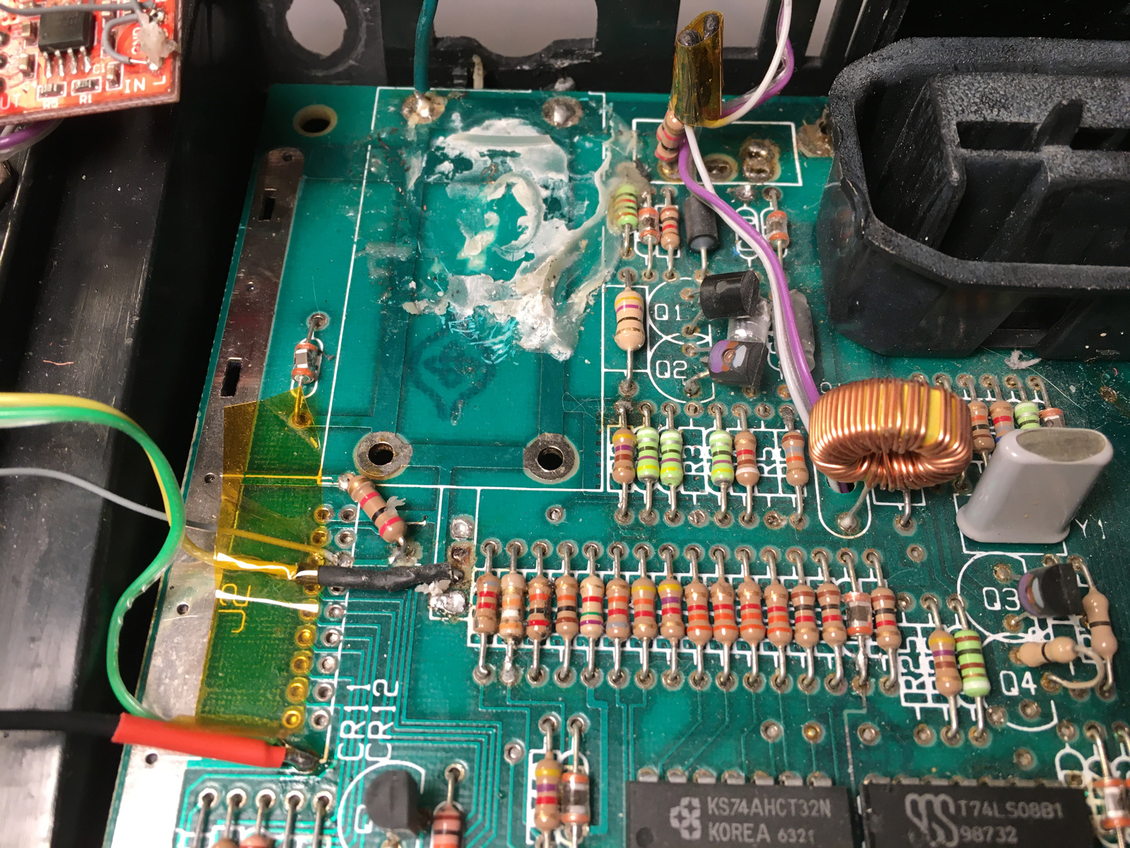
Unfortunately, even though removing the HDMI "mod" did fix the short, it didn't fix the joystick problem.
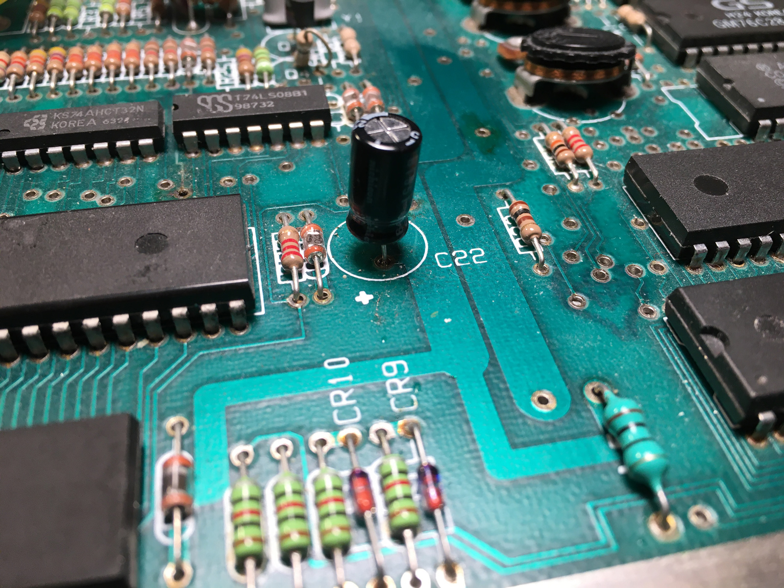
After this, I also installed a recap kit from Console5. I didn't expect it to do anything about the joystick issue, but it was on the "to-do" list.
Yes... the whole case needs a serious cleaning. Also patching - there are a lot of holes in it.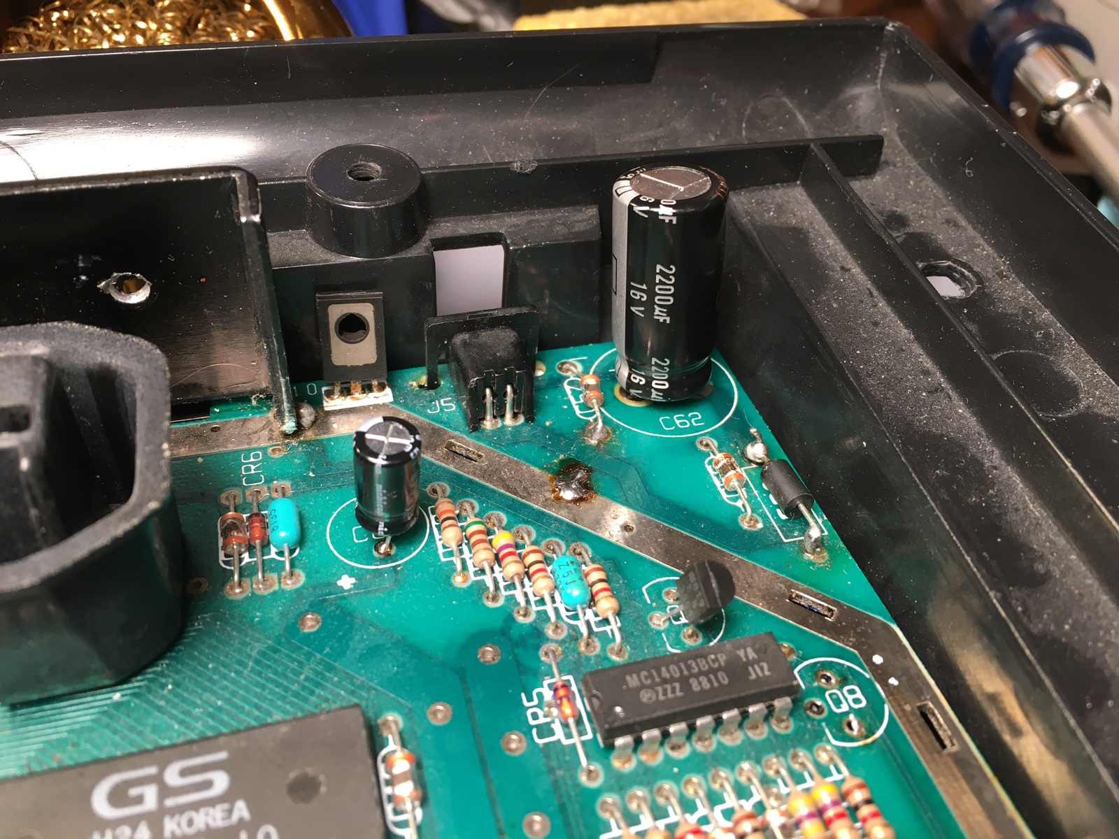
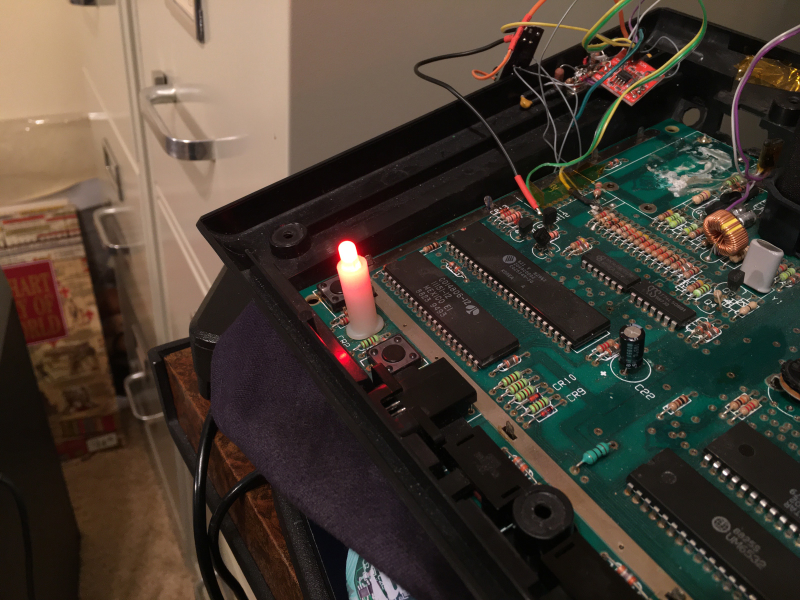
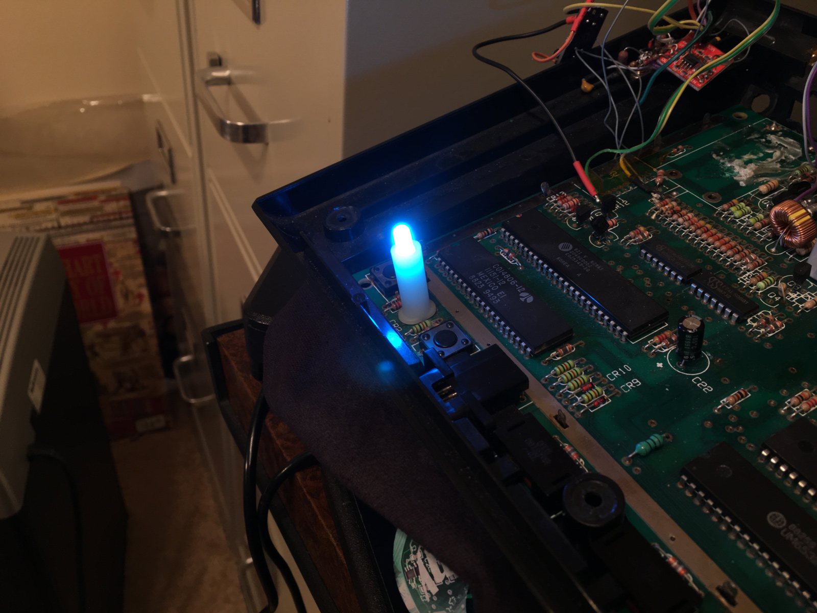
Also on the "to-do" list, was getting rid of that obnoxiously bright "rainbow" LED:
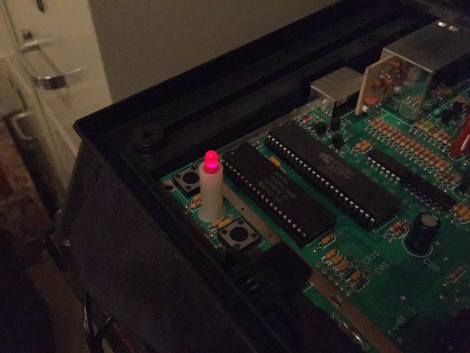
By comparison, here's the original LED in my stock 7800 (I had to adjust my iPhone's exposure to make it appear as dim as it does in real-life):
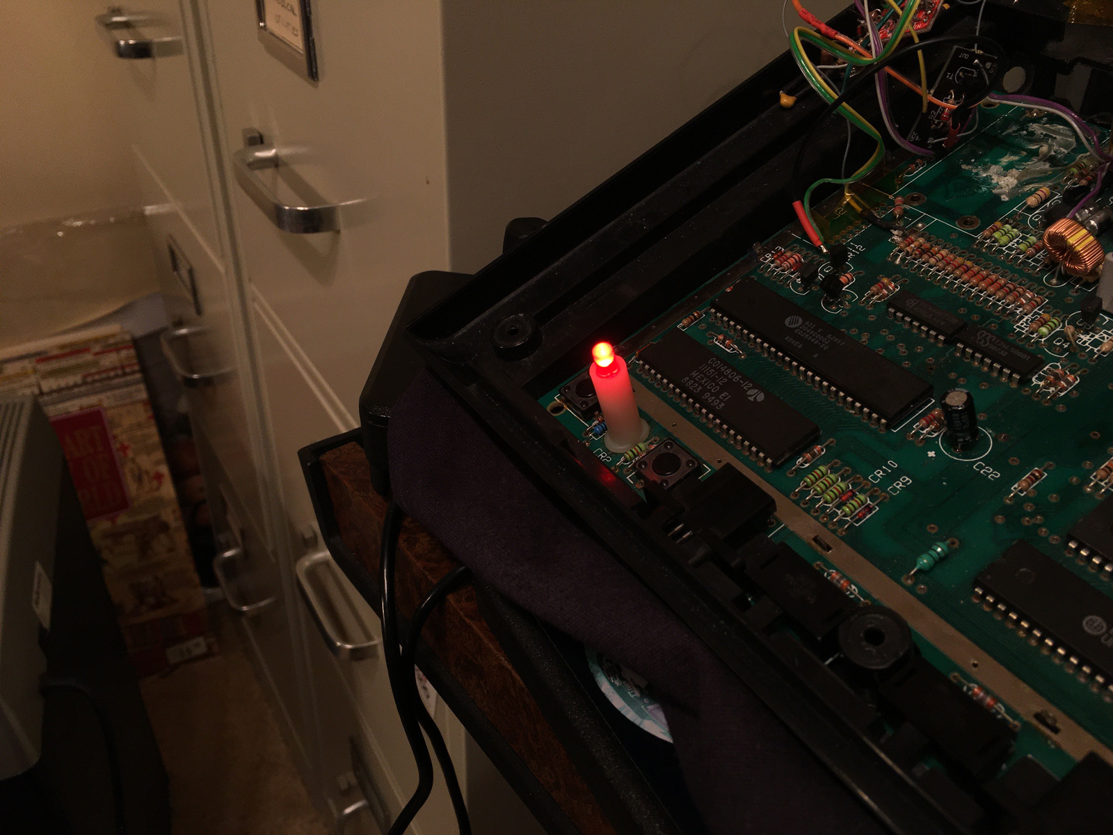
Here's the replacement red LED. Better, but still too bright: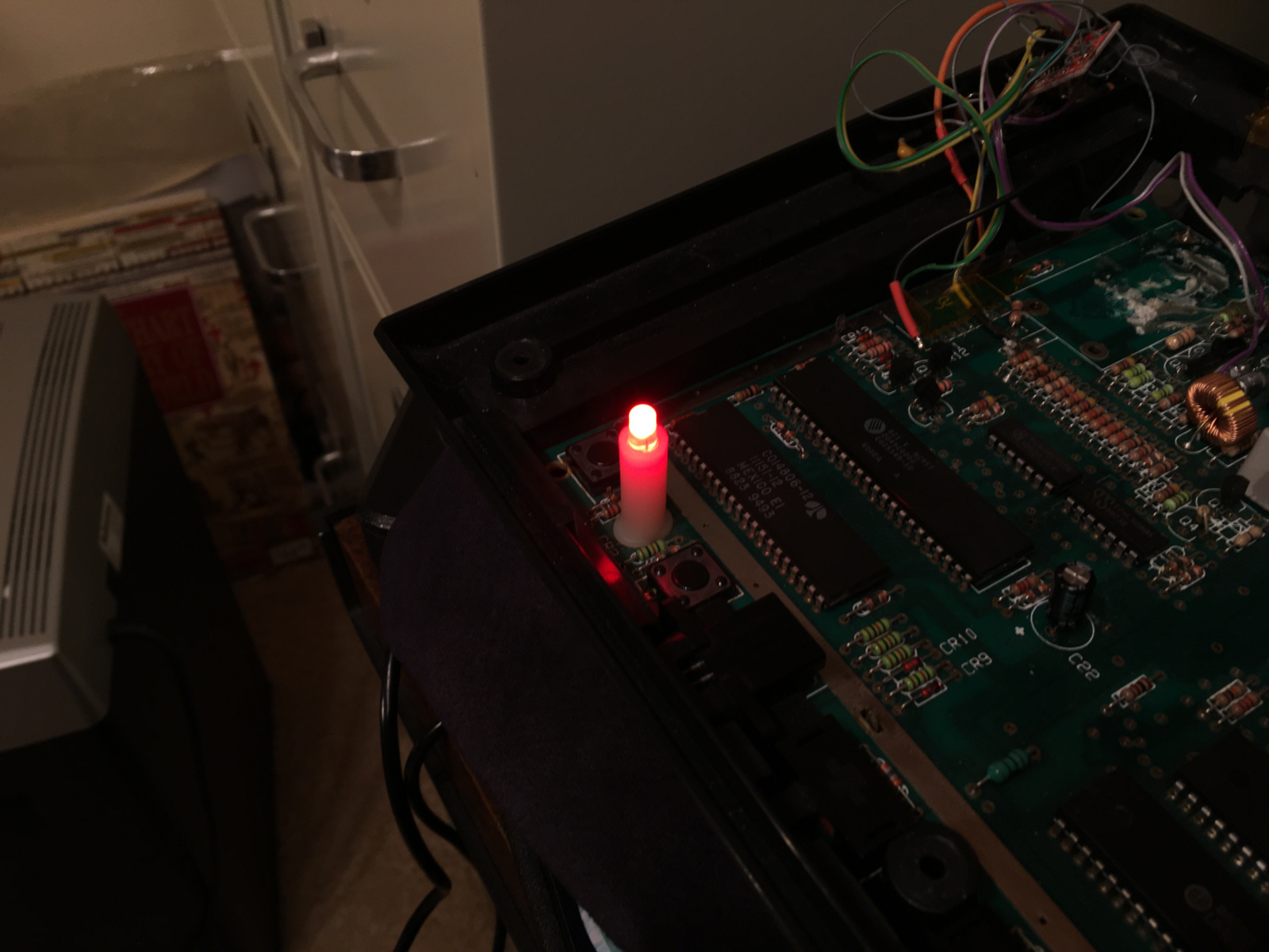
-^CrossBow^- said he usually adds a 460Ω resistor, in place of the stock one to drop the brightness down. I tried that, but felt it was still too bright:
So I stepped it down further, with an 800Ω resistor: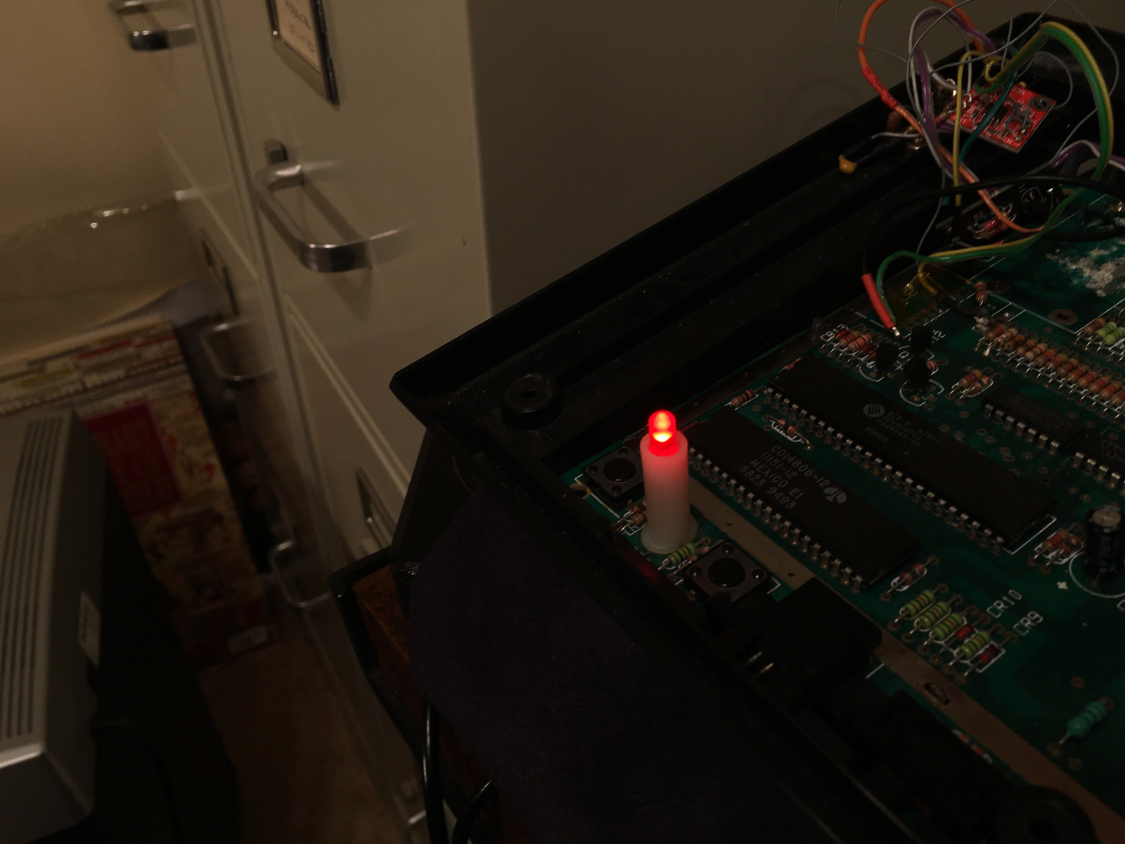
Much better! More like a power indicator, less like Laser Pink Floyd.
Now then, onto the transistors. Both of the ones in question (labeled Q6 and Q8 on the board) are 2N3906 PNP transistors, but I didn't have any spares lying around, so I couldn't just replace them.
So I desoldered those two transistors from my own 7800, so I could test and compare them with the ones from John's console.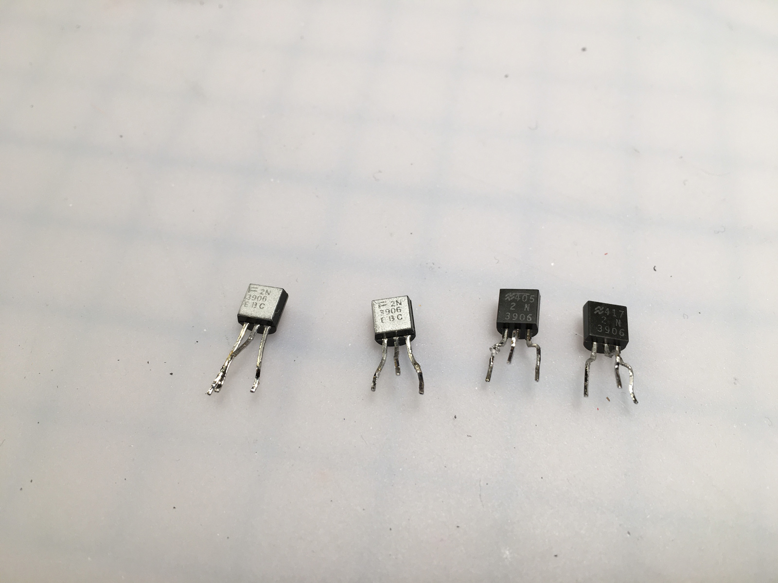
I marked them to keep track of which was which. John's are on the left (white dots), mine are on the right (orange dots):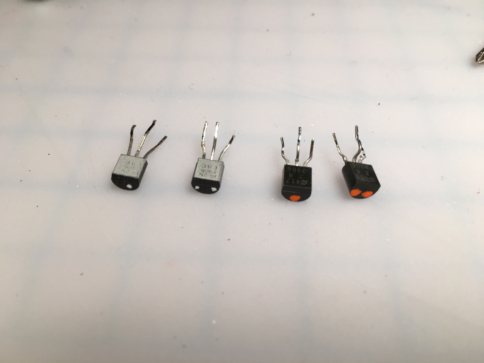
It's been awhile since basic high school electronics ![]() , so I had to look up how to test transistors with a multimeter.
, so I had to look up how to test transistors with a multimeter.
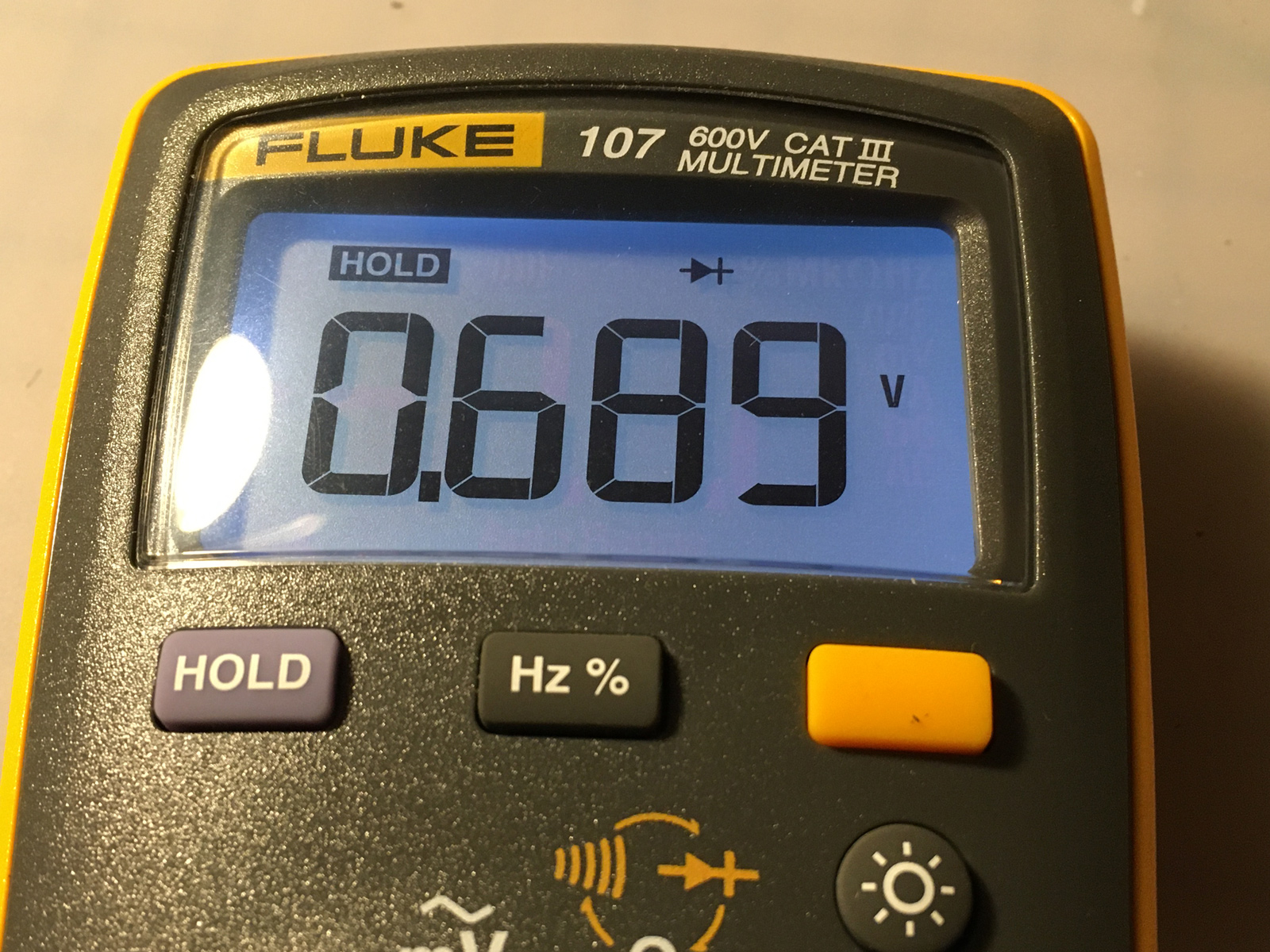
So here are the results from my 7800:
Q6	Collector to Emitter	OL
Q6	Emitter to Base		.691v
Q6	Collector to Base	.686v
Q8	Collector to Emitter	OL
Q8	Emitter to Base		.689v
Q8	Collector to Base	.682v
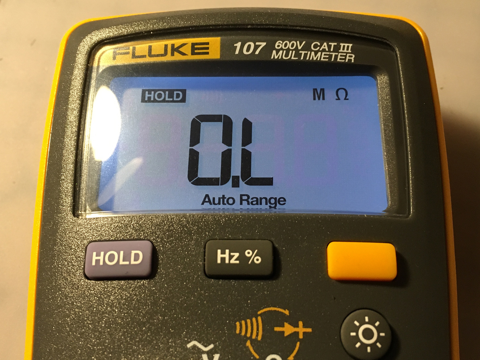
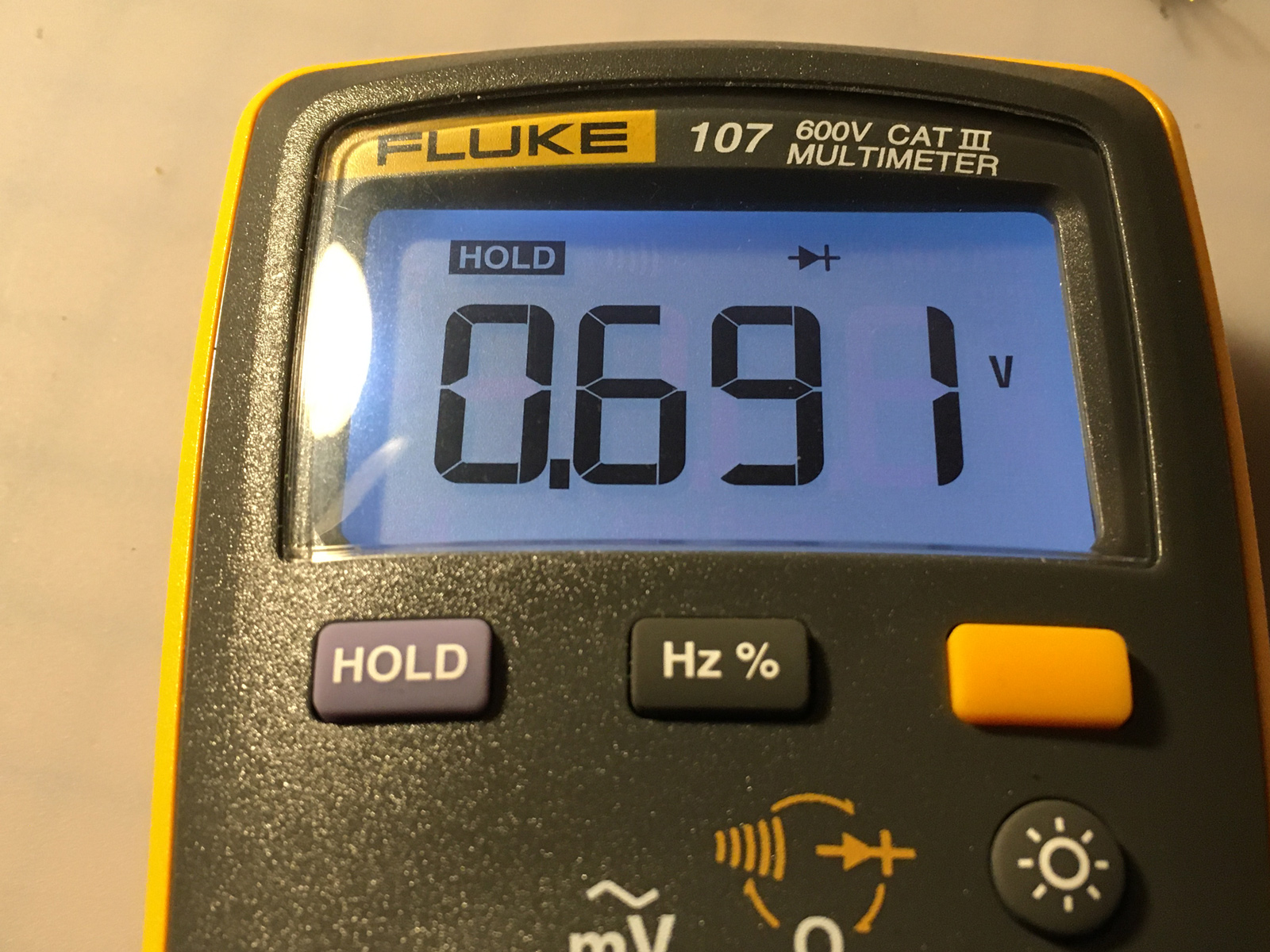
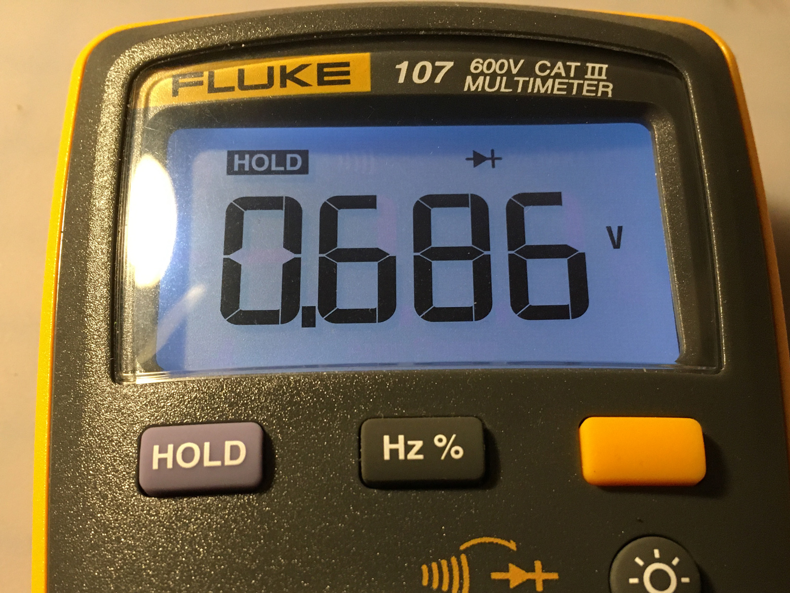
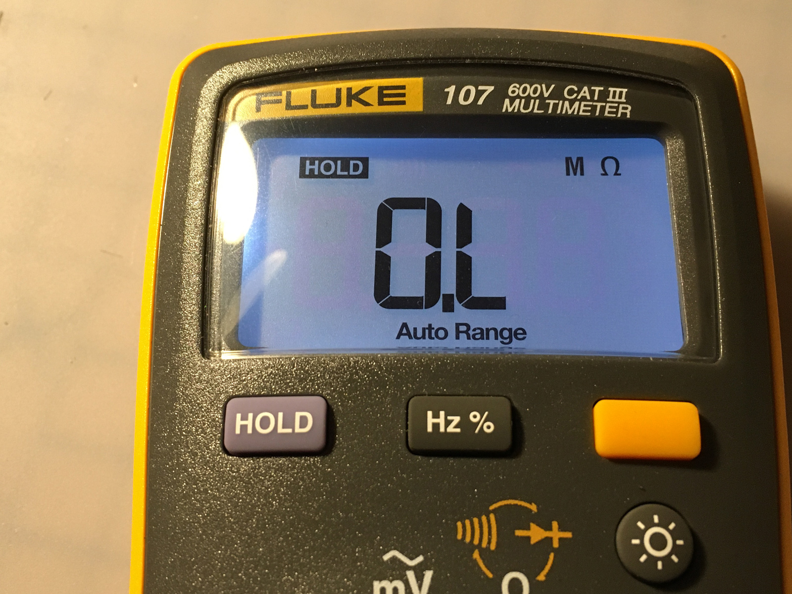
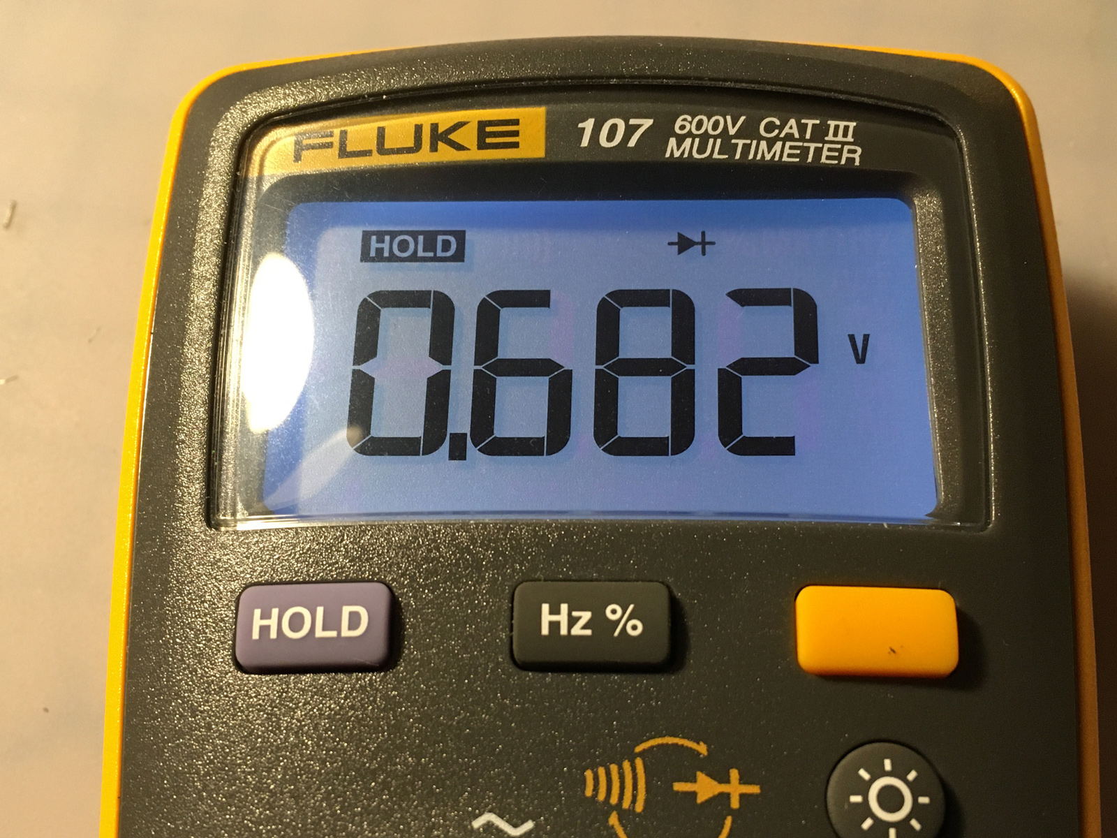
Well, that all looks good.
And from John's 7800:
Q6 Emitter to Collector 11.6Ω
Q6 Emitter to Base .703v
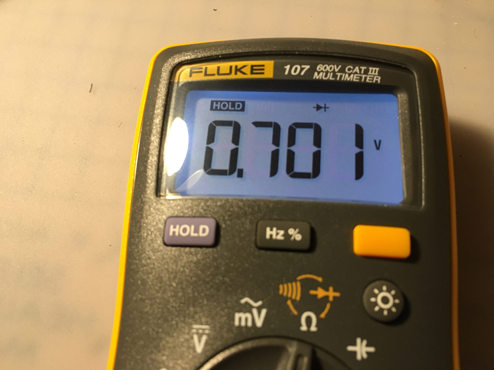
Q6 Collector to Base .701v
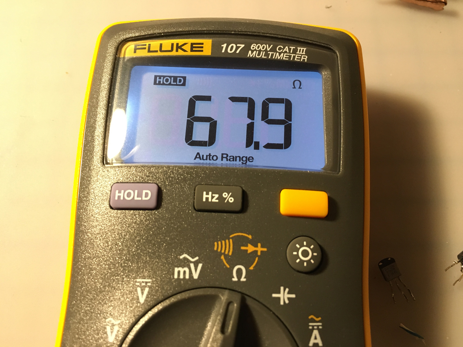
Q8 Collector to Emitter 67.9Ω
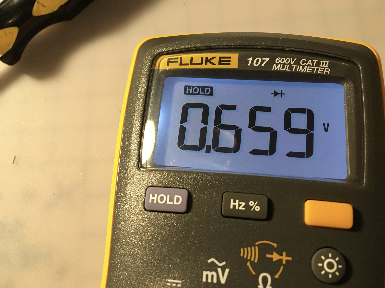
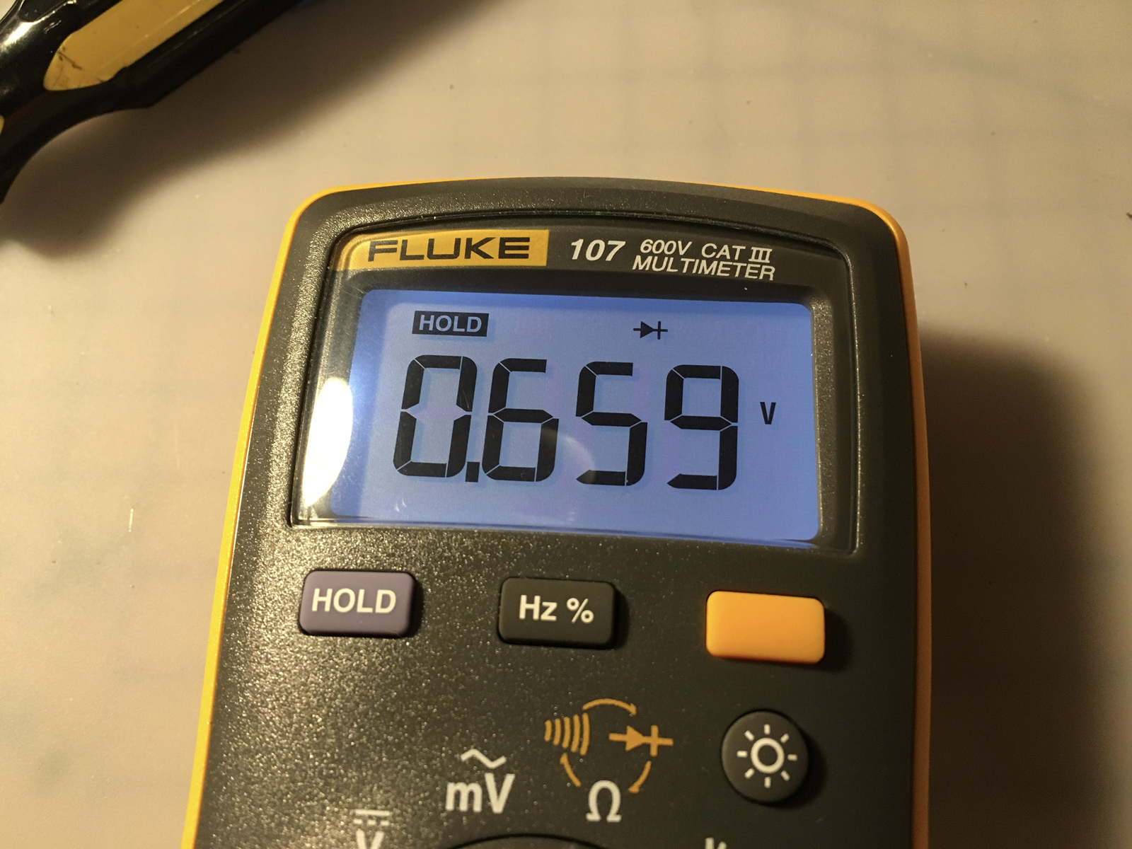
Q8 Emitter to Base .659v
Q8 Collector to Base .659v
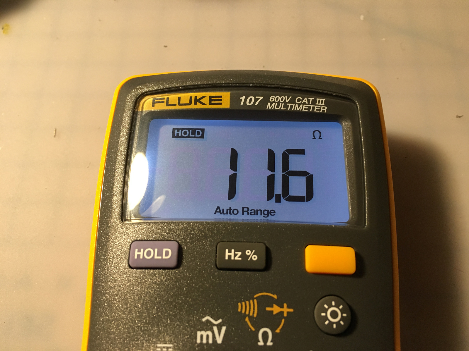
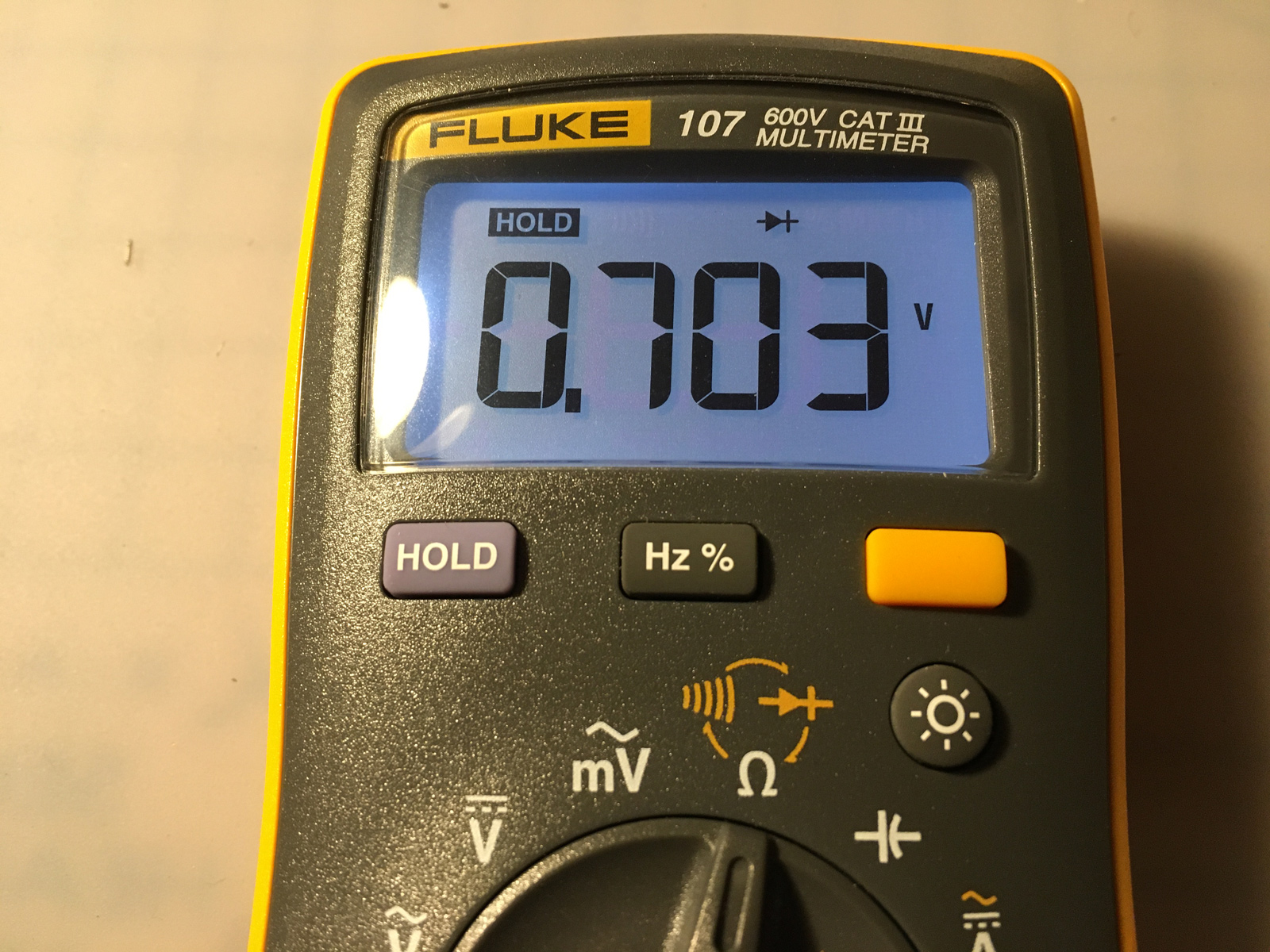
Well, that ain't right.
So, I transplanted my transistors into John's 7800, and re-tested it:
And lo-and-behold, that fixed it! The 7800 Pro-Line buttons now worked properly in 2600 and 7800 modes. Much easier than having to desolder and swap a RIOT.
At least, it was finally working... for all of five minutes. Then I desoldered my transistors, and put them back in my 7800 where they came from. I've ordered some new ones from Mouser (along with some other parts), and will install those... next time.
Published 1/3/23 at 11:46PM
-
 5
5

3 Comments
Recommended Comments