Jump to content
  • entries
    945
  • comments
    4,956
  • views
    1,221,115

The 7800 Mod Mess Mixup Fixup - pt. 5


Nathan Strum

412 views

Well, this blog entry just about ended very differently. :ponder:  But it's all-good now.


So close to the finish line... just a couple more things to do after this. But first, here's where we're at now.


When we last left this poor, abused 7800, I was about to install a UAV mod, using one of -^CrossBow^-'s 7800 UAV Mount Boards


First - I need to install the wires (or a header, but in this case, wires). I soldered the first one, then held each successive wire in place with some little copper clips I picked up somewhere ages ago. Probably Radio Shack. Anyway, they're super-handy.

01-uav-wiring.jpg


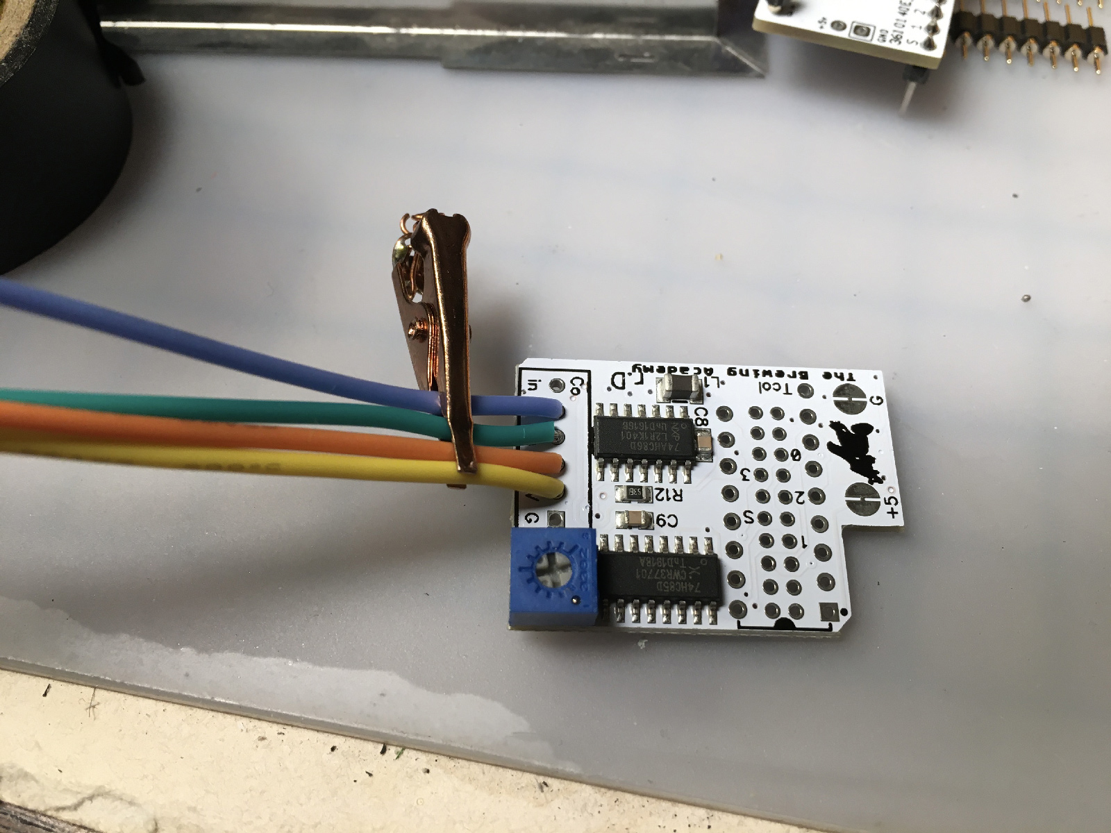
I also recently picked up a bigger magnifier, because age.
02-magnificator.jpg


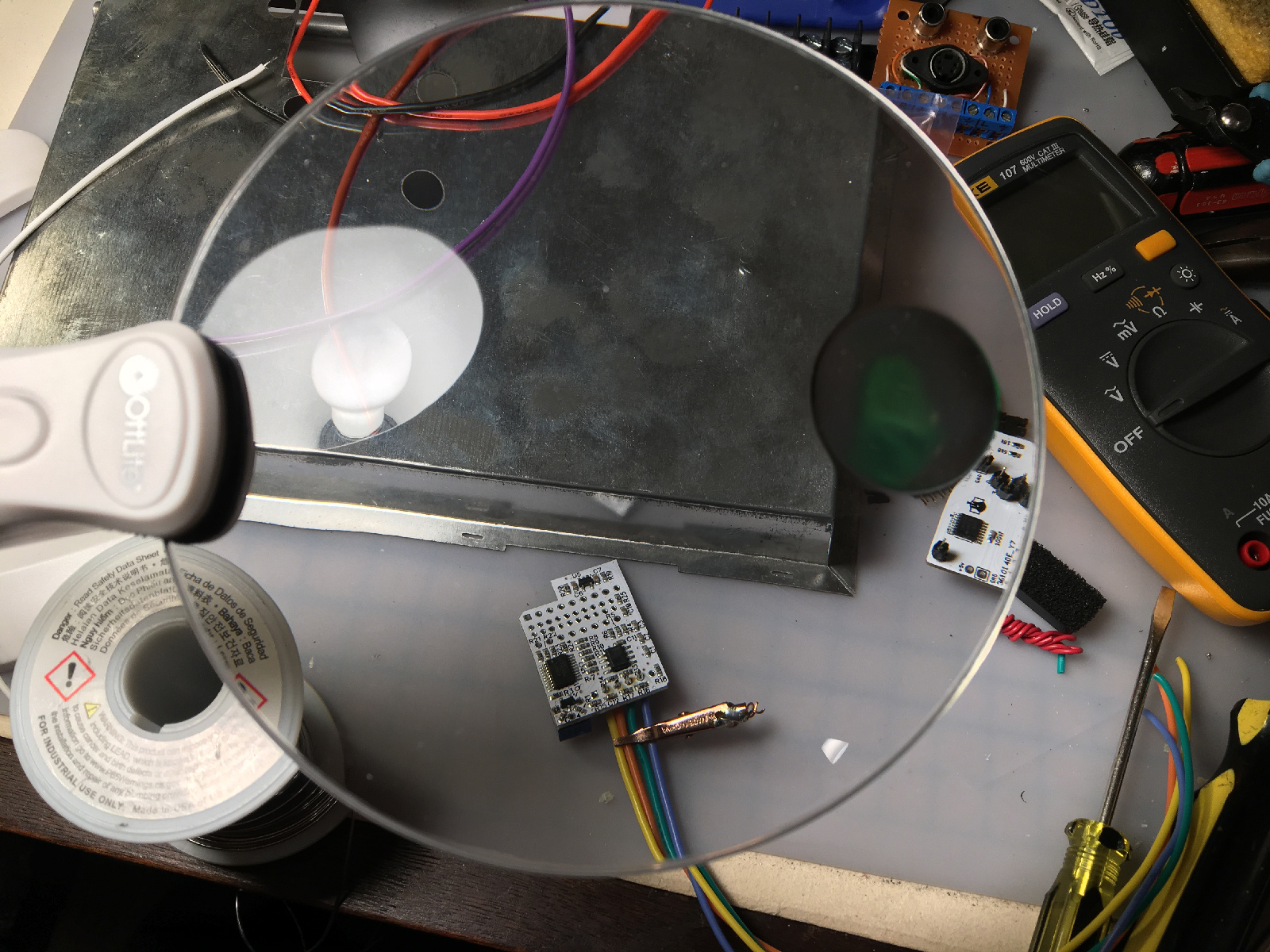
Here they are, all soldered sort-of neatly in place. Note to self: next time you install one of these, switch out your soldering iron tip for a smaller one.
03-uav-wired.jpg


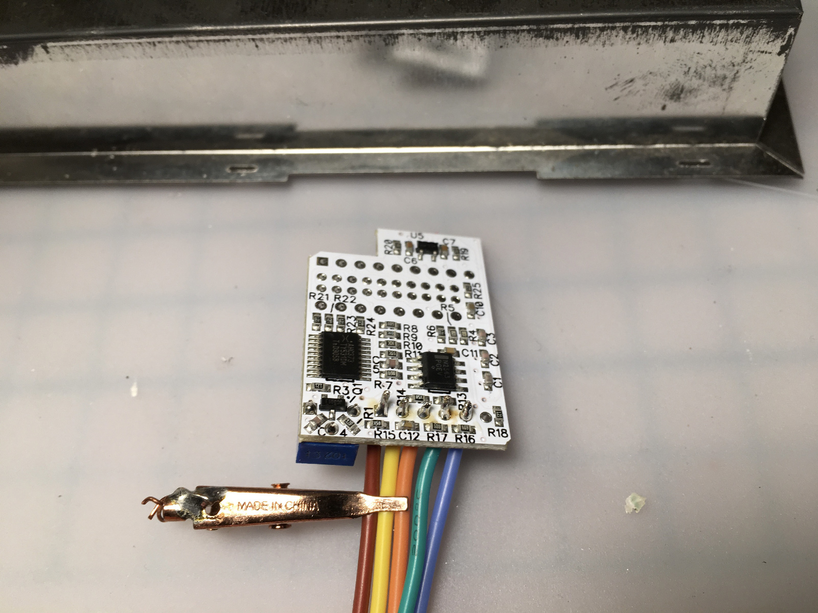
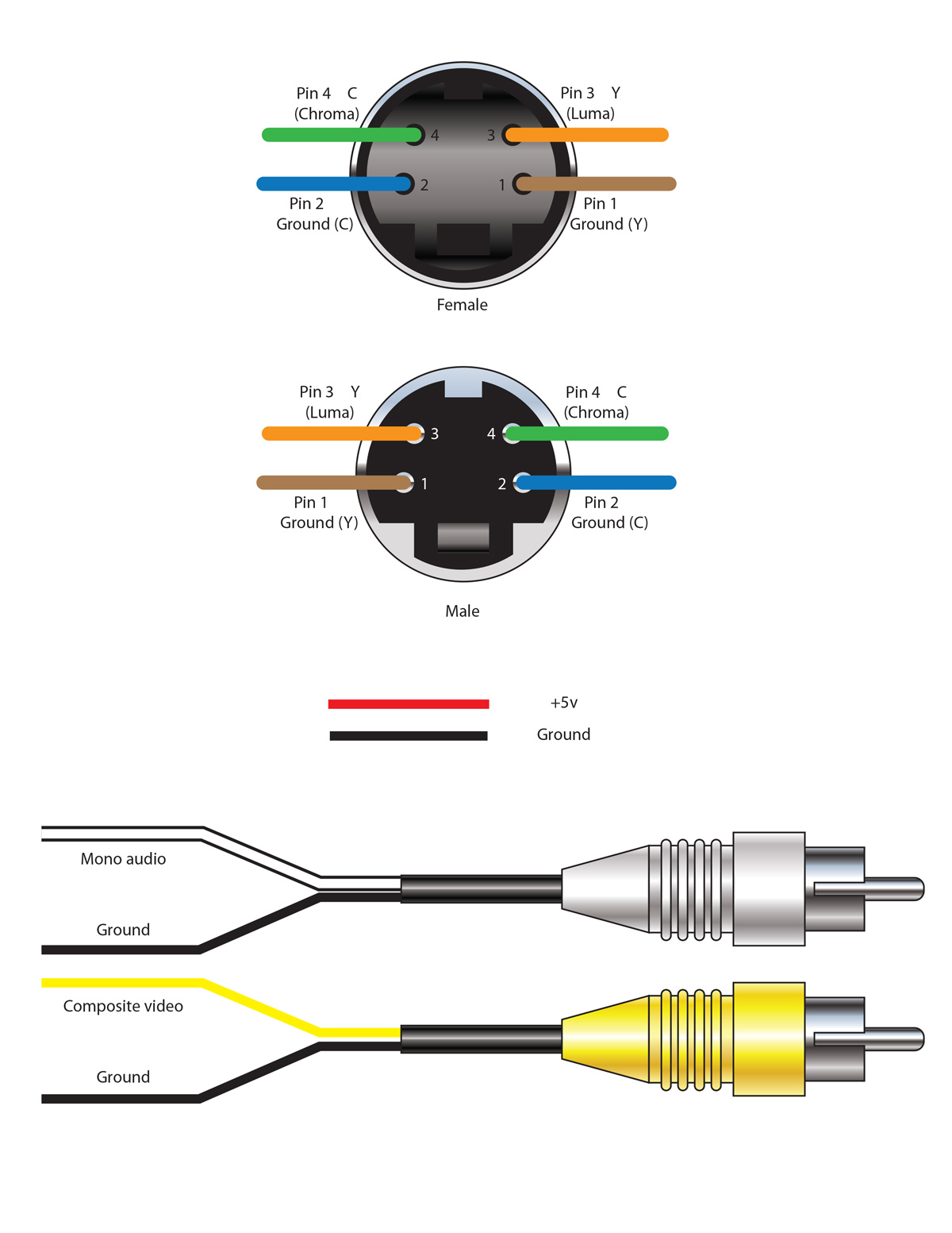
In case you're wondering what each wire color is, here's a diagram I've made so I can be consistent when installing these:

00-wiring-diagram.jpg


Next - I have to add a few wires to the Mount/Chroma Fix/Audio Circuit board:
04-7800-mount-board.jpg


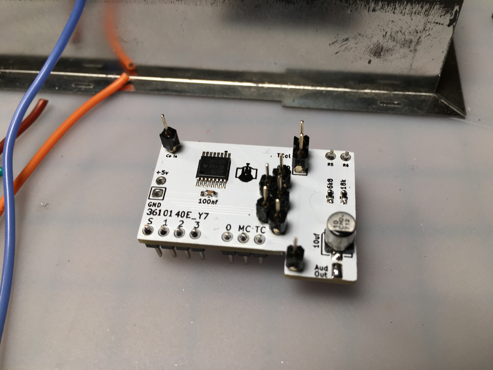
Time to bust out the Radio Shack "Helping Hands" I bought eons ago. The electrical tape keeps the alligator clip from marring things:
05-helping-hands.jpg


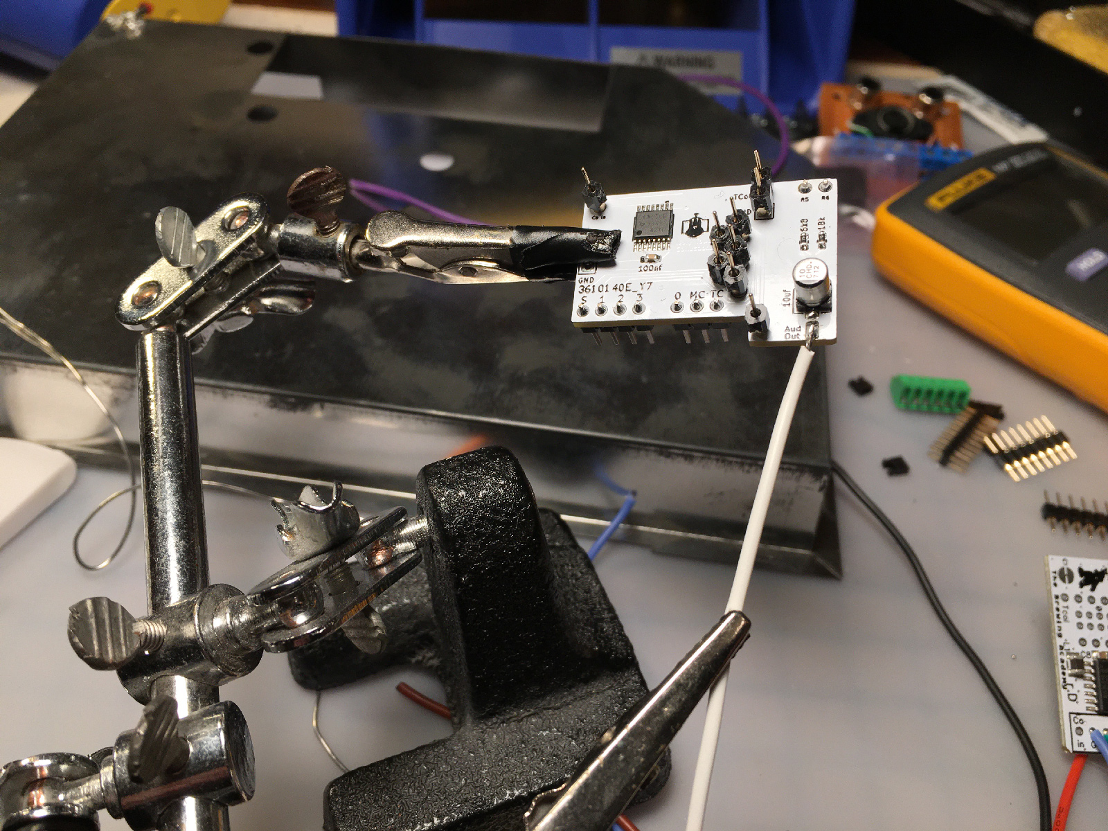
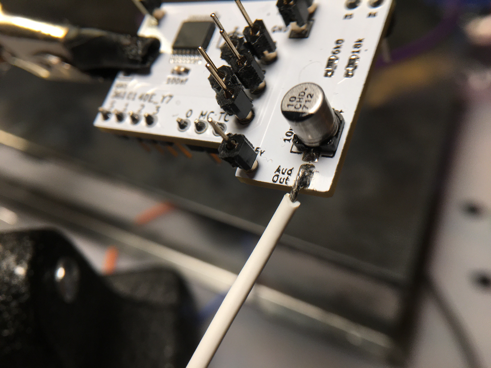
This is a really tiny pad...  but I was able to make a good connection. (As a side note - if I were designing mods/boards and such, I'd make the pads bigger, and space the vias further apart, so people like me who are a bit ham-fisted with soldering irons have a little easier time with them).

06-audio-pad.jpg


And the power wires are in place (they can attach to either board - nice feature there, Jesse!) Everything is all wired up!
07-boards-soldered.jpg


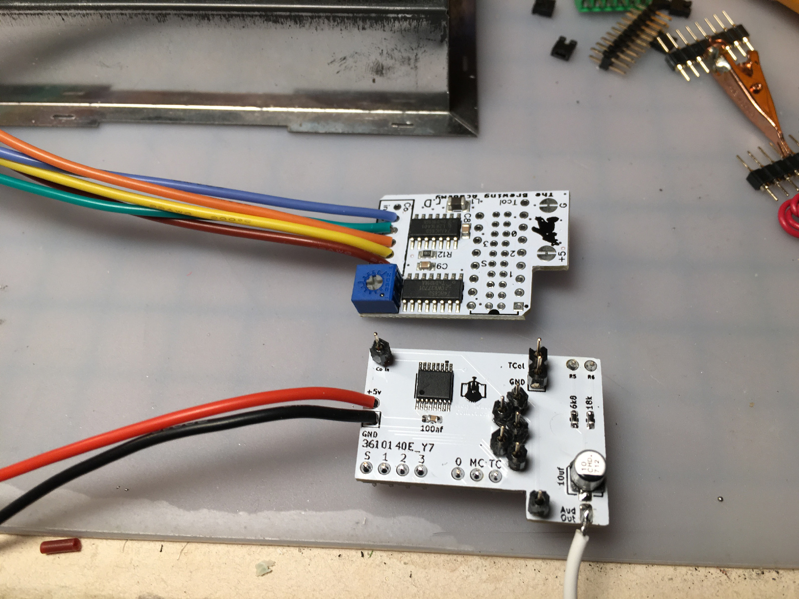
Now at this point, I had a choice to make. The Mount board is designed to sit alongside the resistor legs, and be soldered to them. Alternately, Jesse suggested I could desolder those resistors (since they're for RF, and RF is long gone from this 7800), and just install the mod directly where they used to be using their vias. While that had some appeal, I decided I wanted to leave as much of the 7800 intact, just in case someone, someday wanted to try to put an RF modulator back. Plus, I wanted the practice for my own 7800, and the RF is definitely staying intact there.


One potential downside to soldering the Mount board to the resistors is that Jesse said it would be a bear to remove. Desoldering those connections would be a pain - but I think you could instead just desolder all of the resistors from the board, and pull the entire thing out as a unit. Then you'd have pretty easy access to remove the resistors, and could reinstall them later.


Anyway, in order to solder onto the resistor legs, I needed to reinstall a leg that had been unceremoniously chopped off by the previous modder. So I did that:
08-just-add-lead.jpg


Then used the little clips to hold the audio side in place:
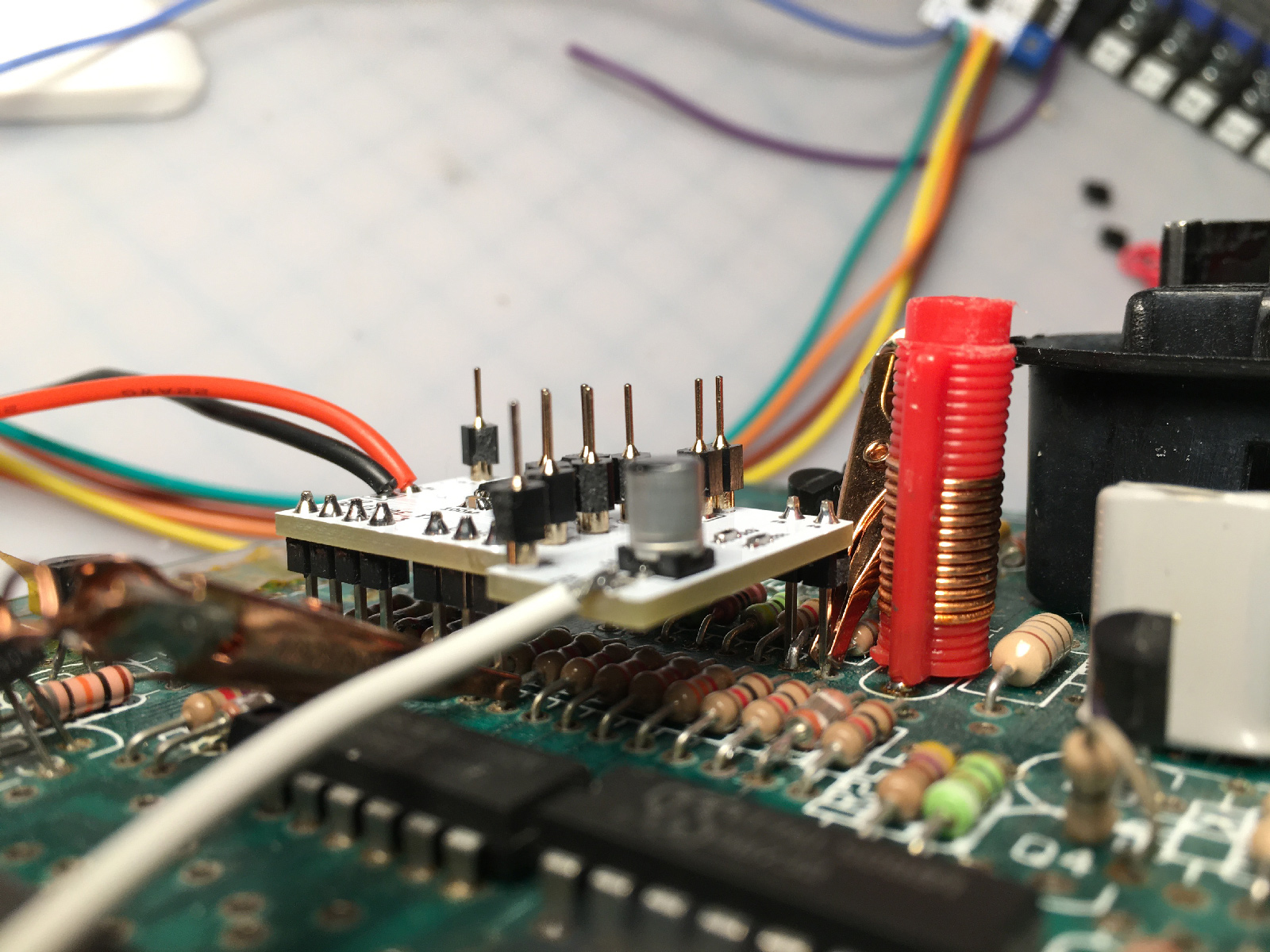
09-audio-clipped.jpg


And the video side:
10-video-clipped.jpg


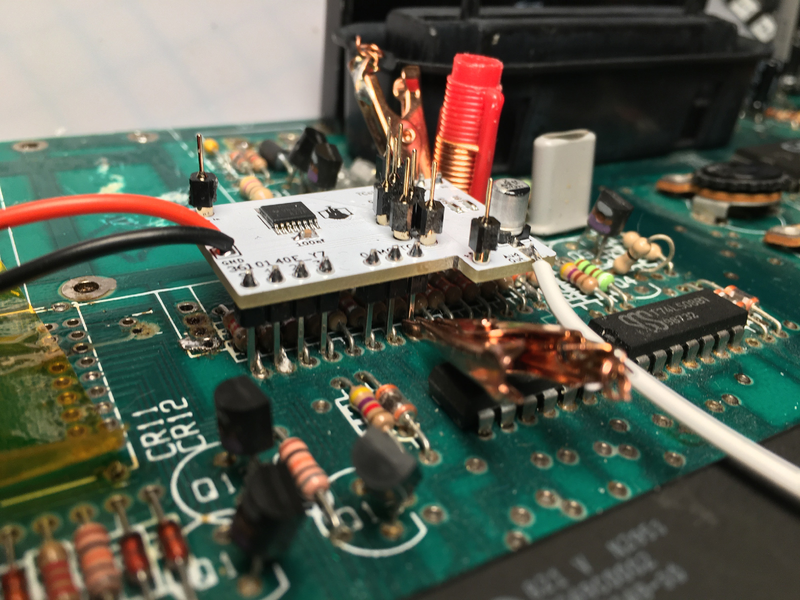
Then, I soldered everything up (note to self: re-read previous note about installing a smaller soldering iron tip next time):
11-video-soldered.jpg


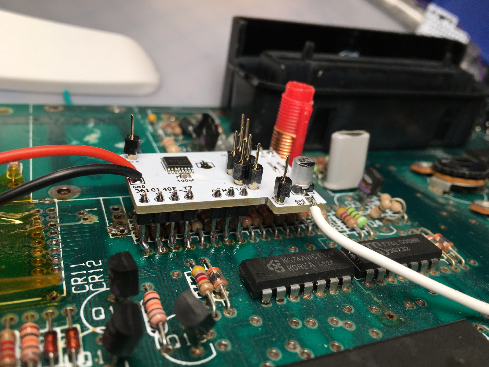
The audio legs were particularly hard to reach. Removing the resistors and just plugging the board in their place would make soldering easier - but you'd have to go through all of the desoldering first.
12-audio-soldered.jpg


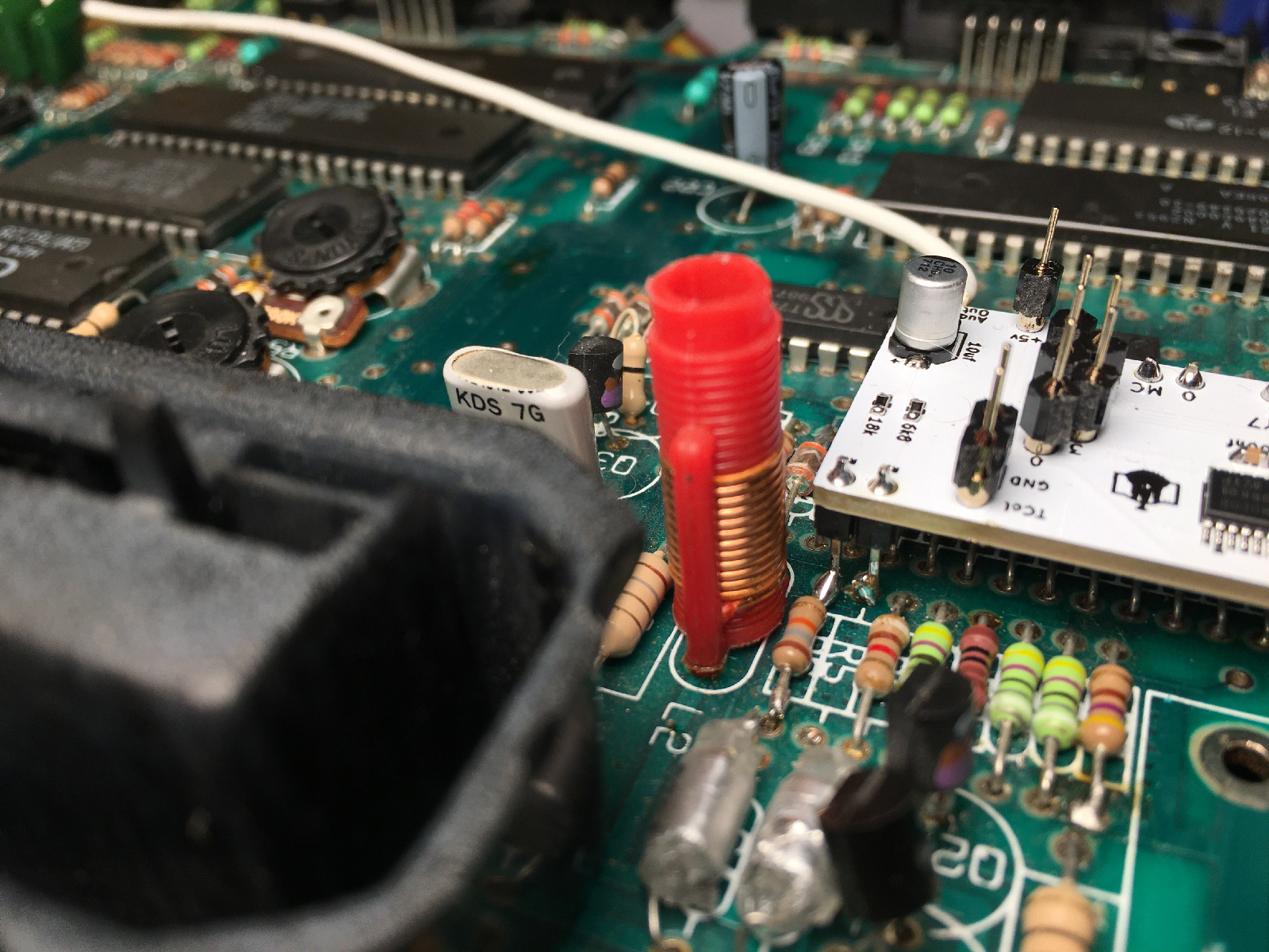
But eventually, I got the board in place:
13-7800-mount-finished.jpg


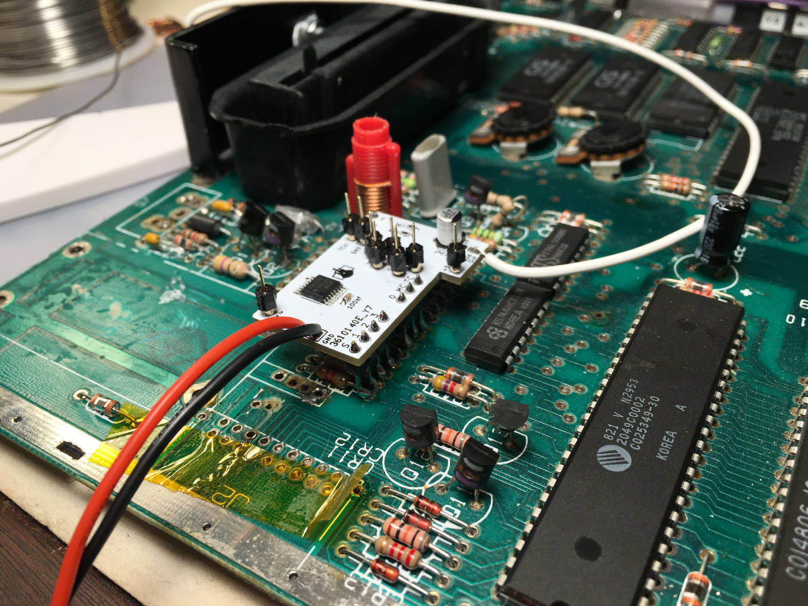
Now, to add the UAV board on top (again with the clips to hold things in place):
14-uav-clipped.jpg


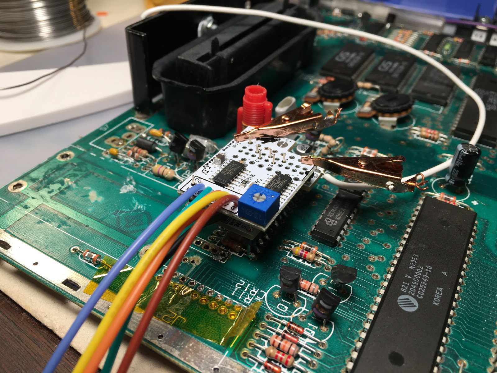
And soldered! (Note to self: soldering. iron. tip. smaller. next. time.)
15-uav-soldered.jpg


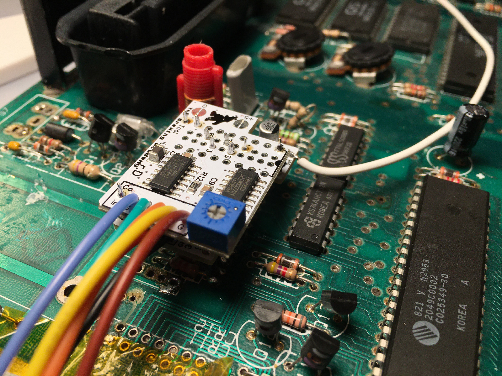
I went through and tested continuity on everything, to make sure it was all properly connected. Some points weren't easily reachable, but that's easy to fix - just wrap a thin piece of wire around your multimeter probe (add tape if necessary) and you can reach pretty-much anything:
16-continuity-in-a-tight-spot.jpg


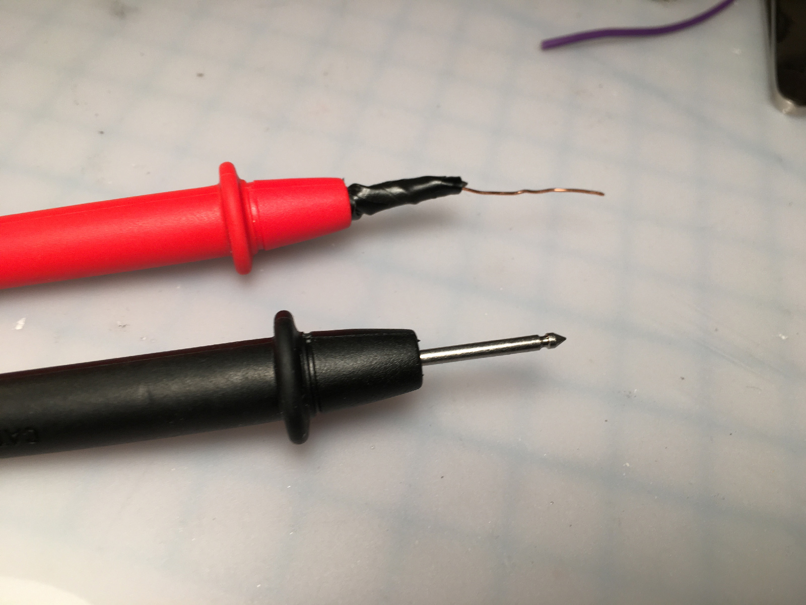
Then, I connected the power and ground. There are a couple of points closer than this to get power from, but the previous modder outright ruined them. For some reason. But this worked fine (they're poked through, and soldered from the underside):
17-just-add-power.jpg


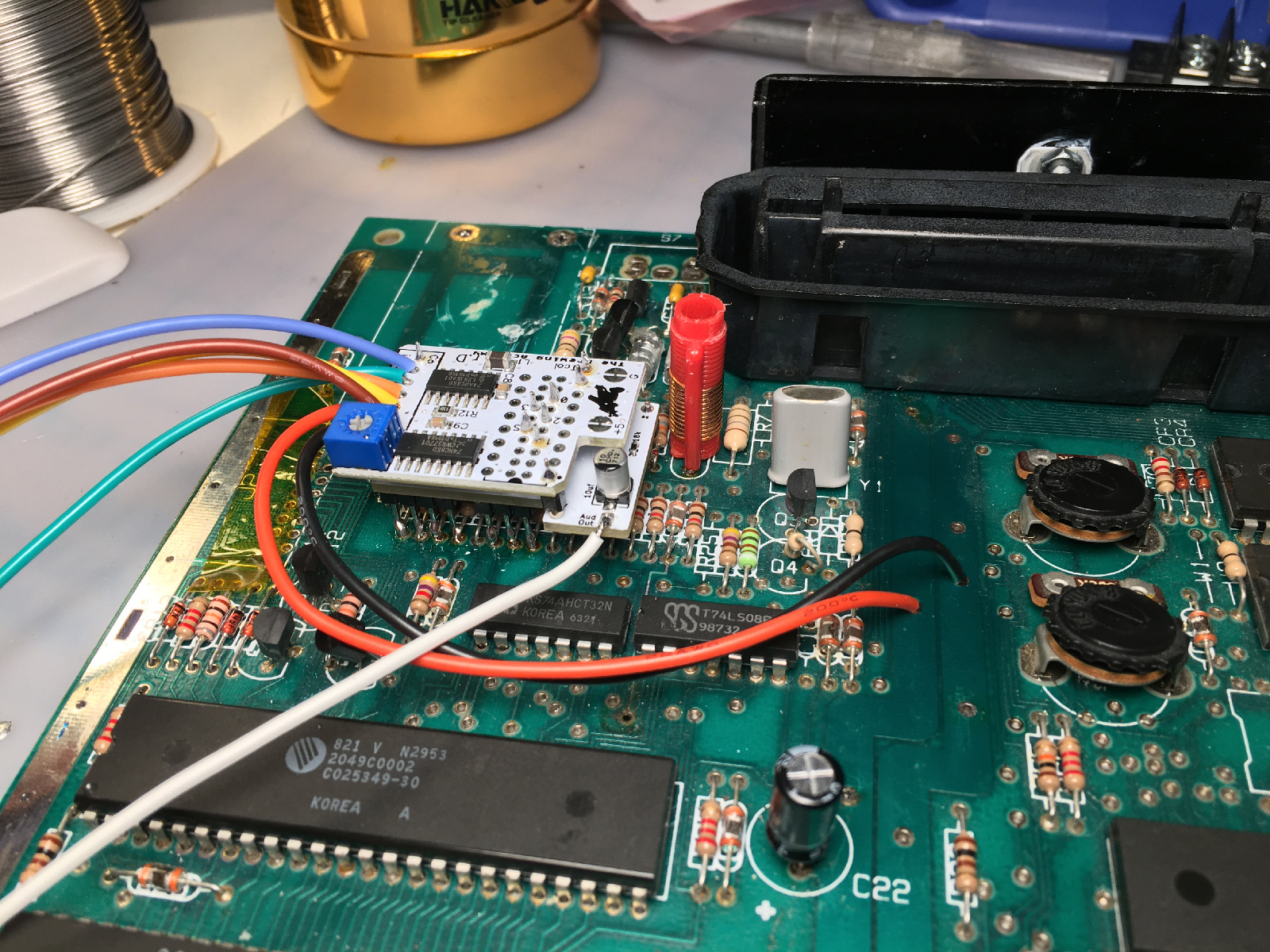
Right! Now to test! I grabbed my handy test board, and wired it up. Usually I have separate left and right audio, but this mod is mono, so I repurposed one of the RCA jacks as composite video (for reasons which will be revealed eventually):
18-test-board.jpg


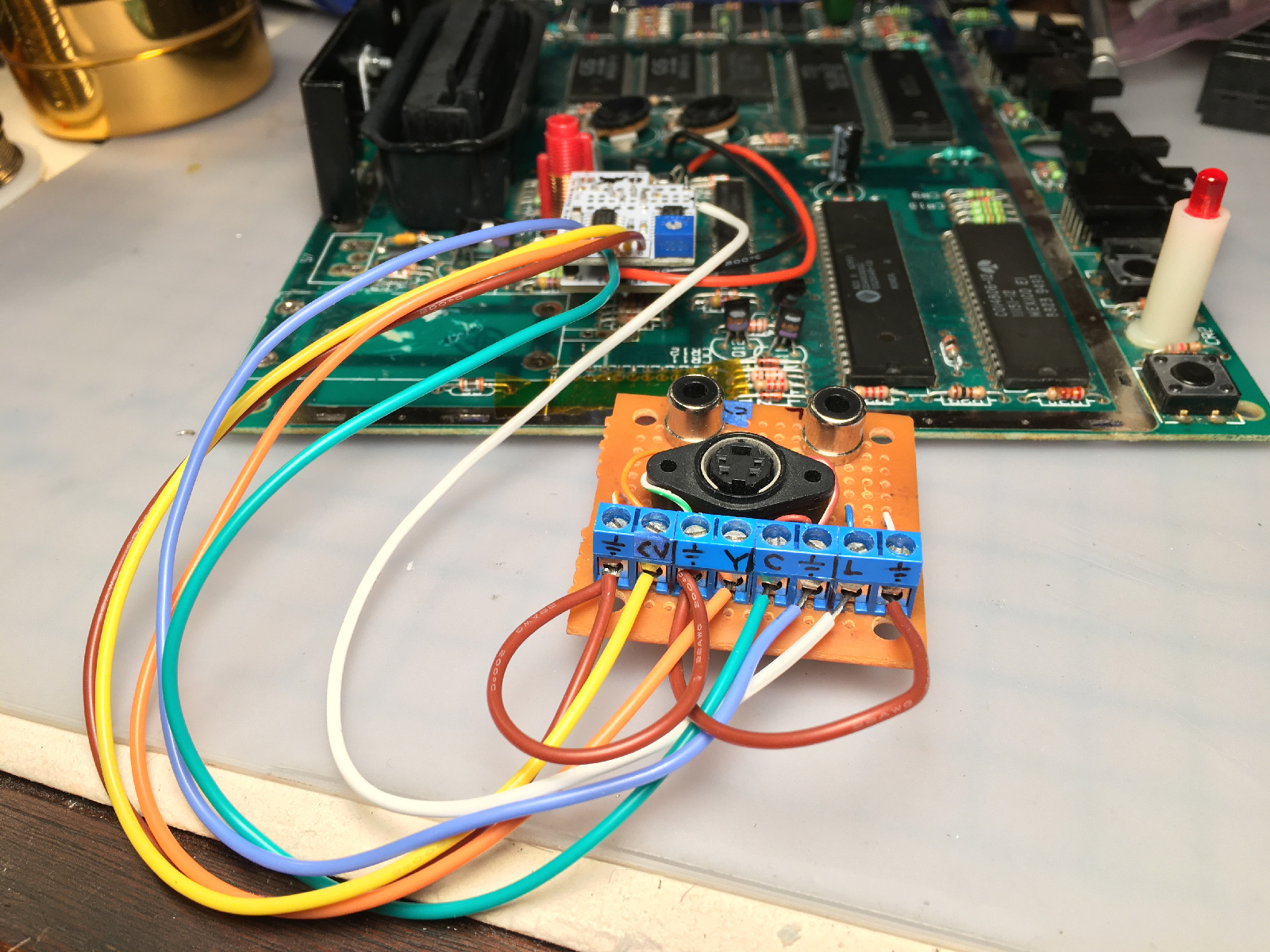
Much to my surprise, it booted up first try! Looked great, too!
19-it-boots.jpg


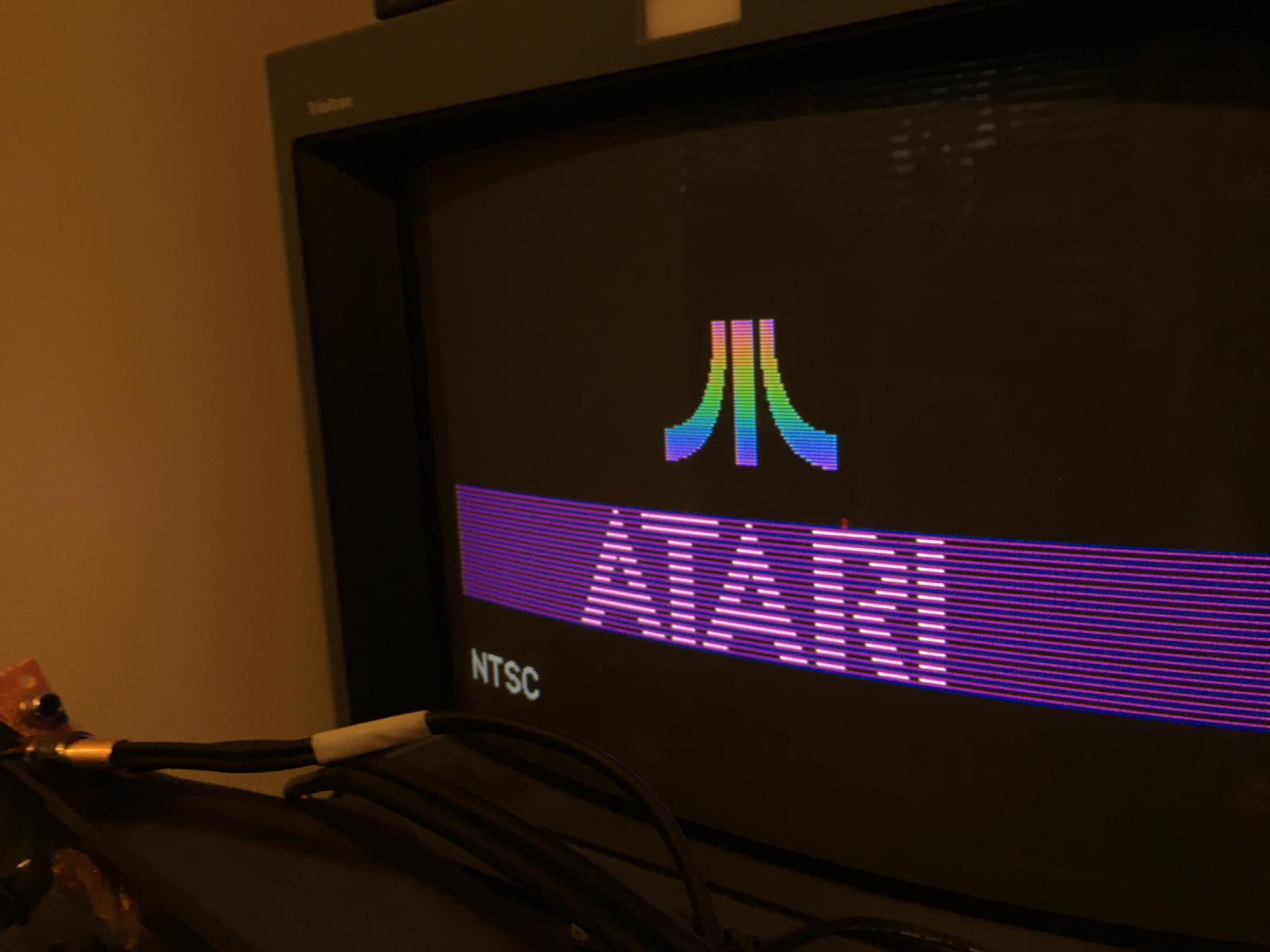
Nice, clean, crisp display! And it's not totally washed out by the LED anymore, either!
20-7800-testing.jpg


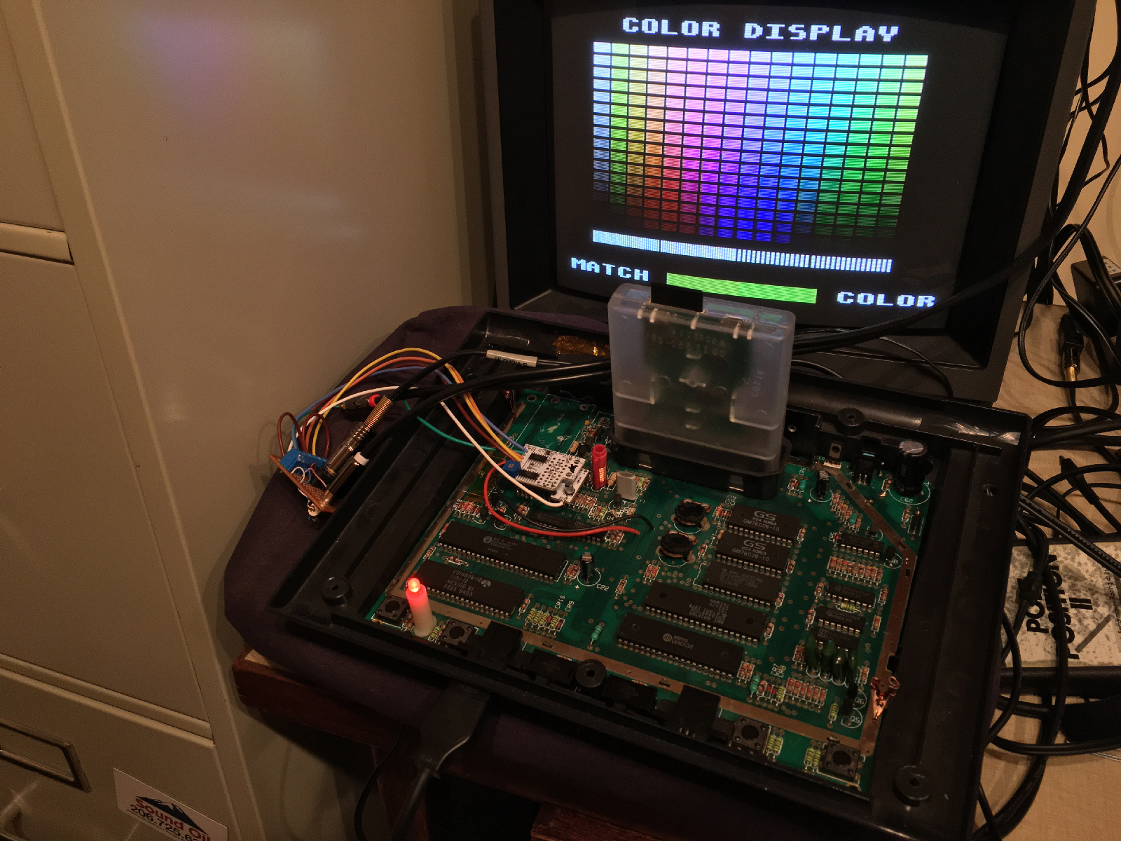
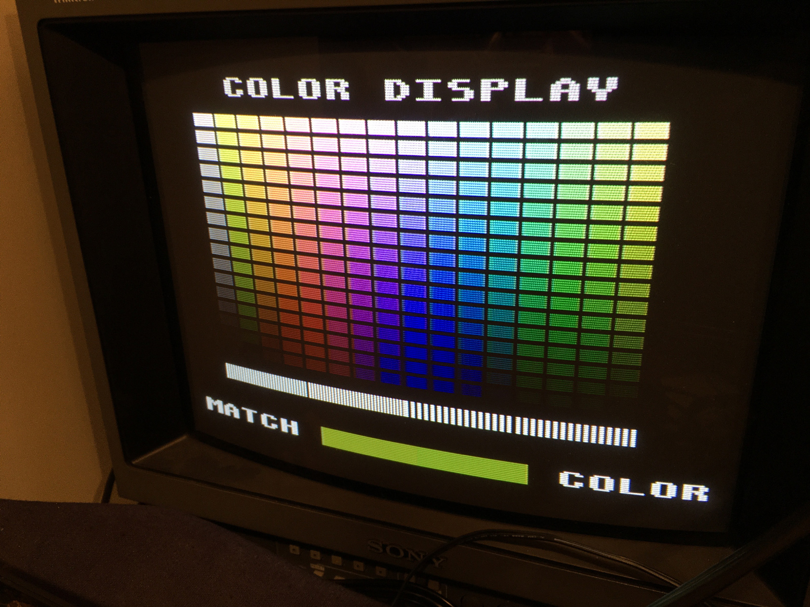
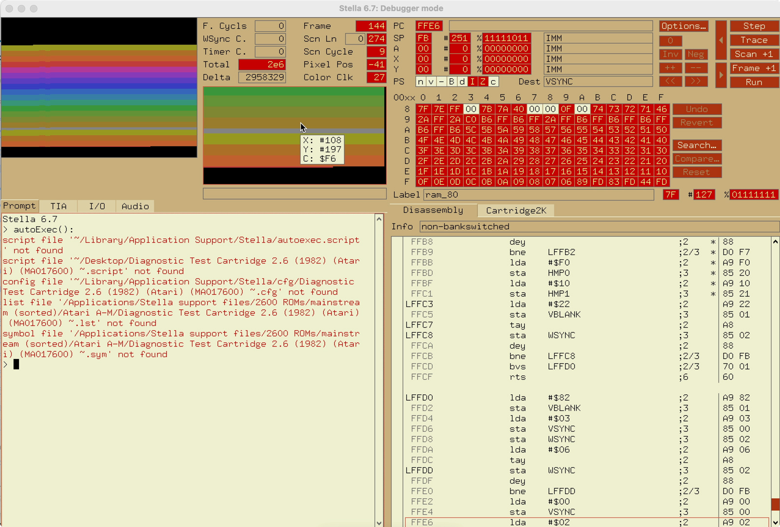
But... here's a question I have for all o' you tech-heads out there, and this has been bugging me for years. This 7800 Utility ROM says to "Match Color" between both sides of that bottom color bar (note: I haven't made any color adjustments):

21-colors-close-up.jpg


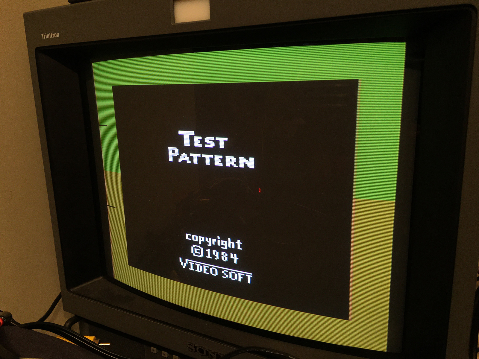
Similarly, the 2600 Color Bar Generator instructions also says to match the two background colors at the title screen:

color_bar_cart.JPG


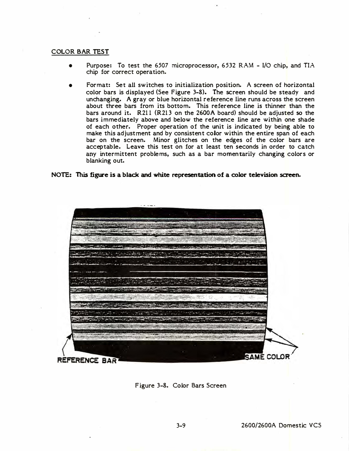
The 2600 field service manual has somewhat contradicting instructions for Atari's Diagnostic Cart, saying to adjust the colors so "the bars immediately above and below the reference line are within one shade of each other." But in the diagram, it points to them and says they should be the "same color".

2600_field_service_manual-36.jpg


Here it is, running on this 7800:

2600_diagnostic_cart.JPG

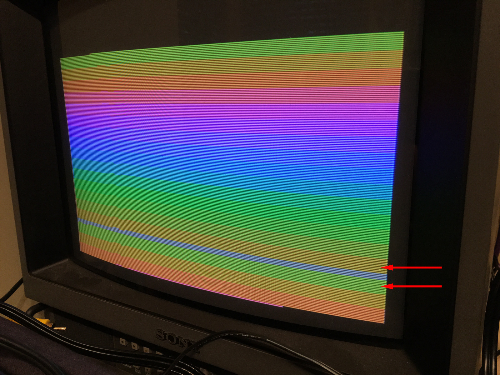
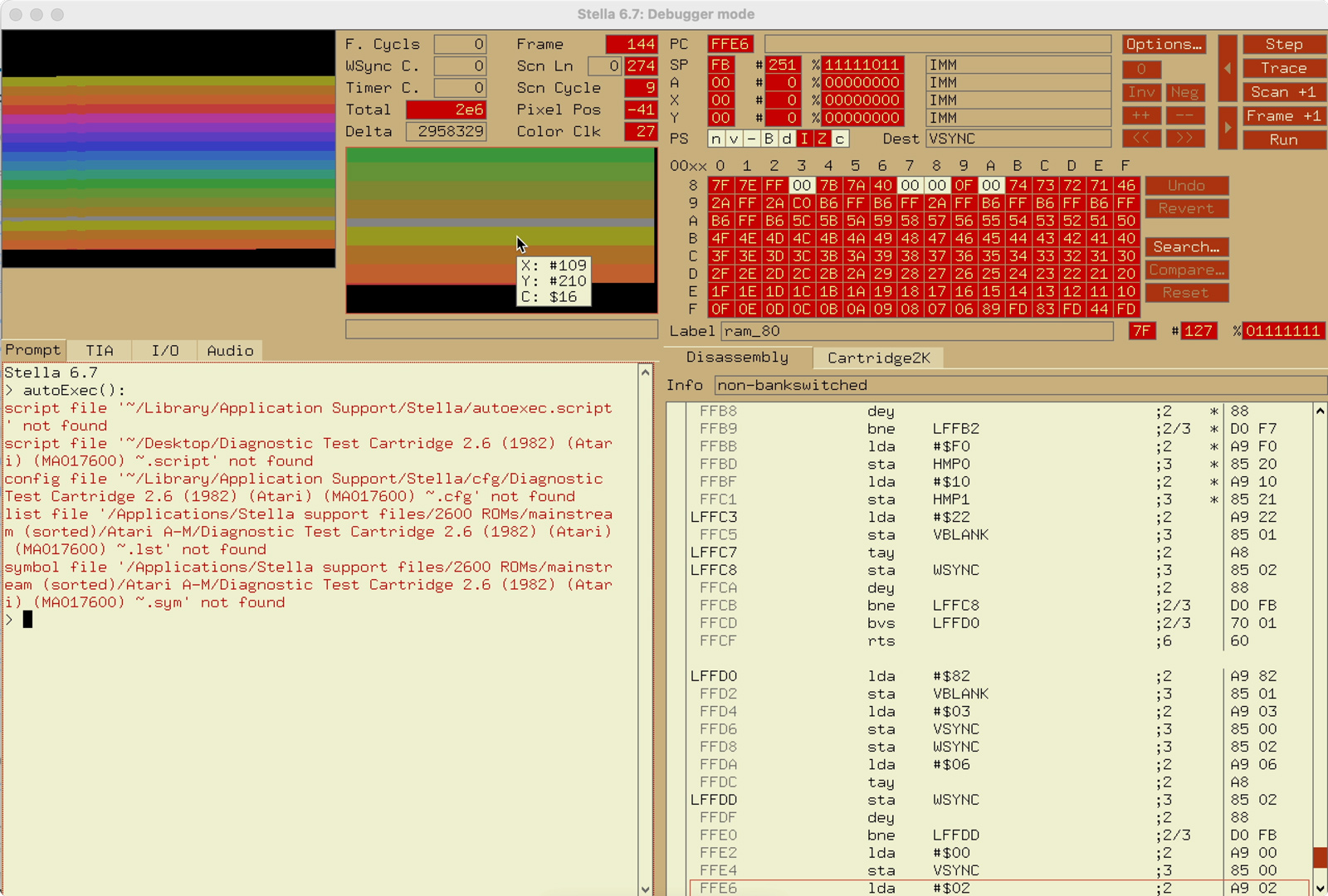
Maybe I'm being picky, but "within one shade" is not the same as "same color". More to the point, these aren't the same color. Stella shows the top color as F6, and the lower one as 16:

stella-f6.jpg

stella-16.jpg

So the question is... is the whole "match these two colors" thing wrong? Seems to me, if they're different colors, they shouldn't match. I wonder if Atari put that in their service manual as a quick "close enough" adjustment instruction, and everyone has just copied it ever since? The problem I've found, is that when I've adjusted 2600's so those two colors match, everything is shifted too much to be green. The browns effectively disappear from the palette. I don't think that would've been the original designers' intent.


Wonder who we could ask about this? :ponder: 


Anyway... back to the 7800.


While the video worked first time out... sadly, the audio was not so lucky. As I ran the audio test on the 7800 Utility ROM, I got zip. Nada. Nothing. At least, not from the TIA side of things.
22-no-tia-audio.jpg

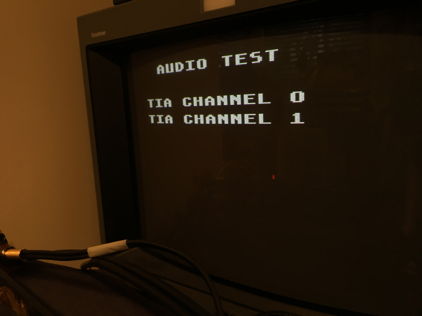
Great. So... what did I break? The TIA audio worked with the earlier mod - but that was completely ripped out and gone now. Did I mis-wire something? Fry the audio board? Is the TIA borked? Is some component still missing?


I thought at this point, I'd just end this blog entry with non-working audio, and see if alex_79 or -^CrossBow^- or someone would chime in with some ideas.


But... :ponder: 


Then I thought, "I wonder if the POKEY works?" So I fired up Ballblazer, and the audio there worked! (Love the THX-like intro sound.)
23-pokey-is-fine.jpg


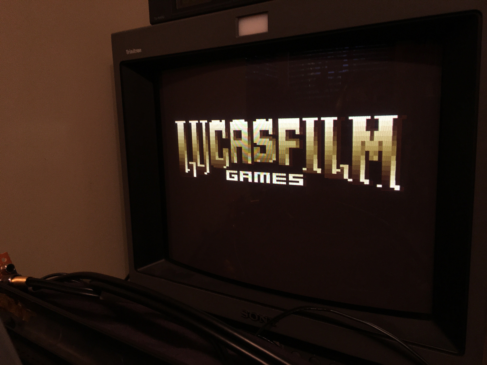
Okay. The audio board is okay. My output wiring is okay. The stuff I replaced earlier (C10 and R5) are okay because they tie into the cartridge port for the POKEY.


The TIA audio just isn't getting where it needs to go. So I dug through the schematics, and started tracing. Pins 12 and 13 of the TIA are combined, and then eventually run over to the base of C14. Pins 12 and 13 were tied into directly for the previous mod. So lets see where that leads us...
24-backside-of-the-tia.jpg


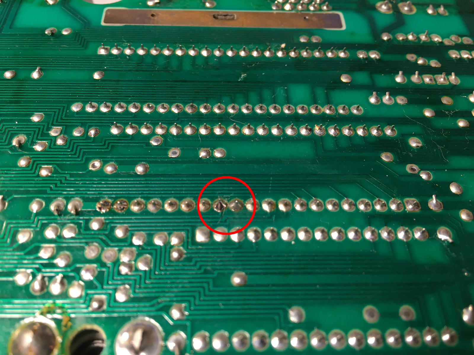
Hmmm. A hole. There's not supposed to be a hole there (I checked this against my non-mutilated 7800):
25-missing-piece.jpg


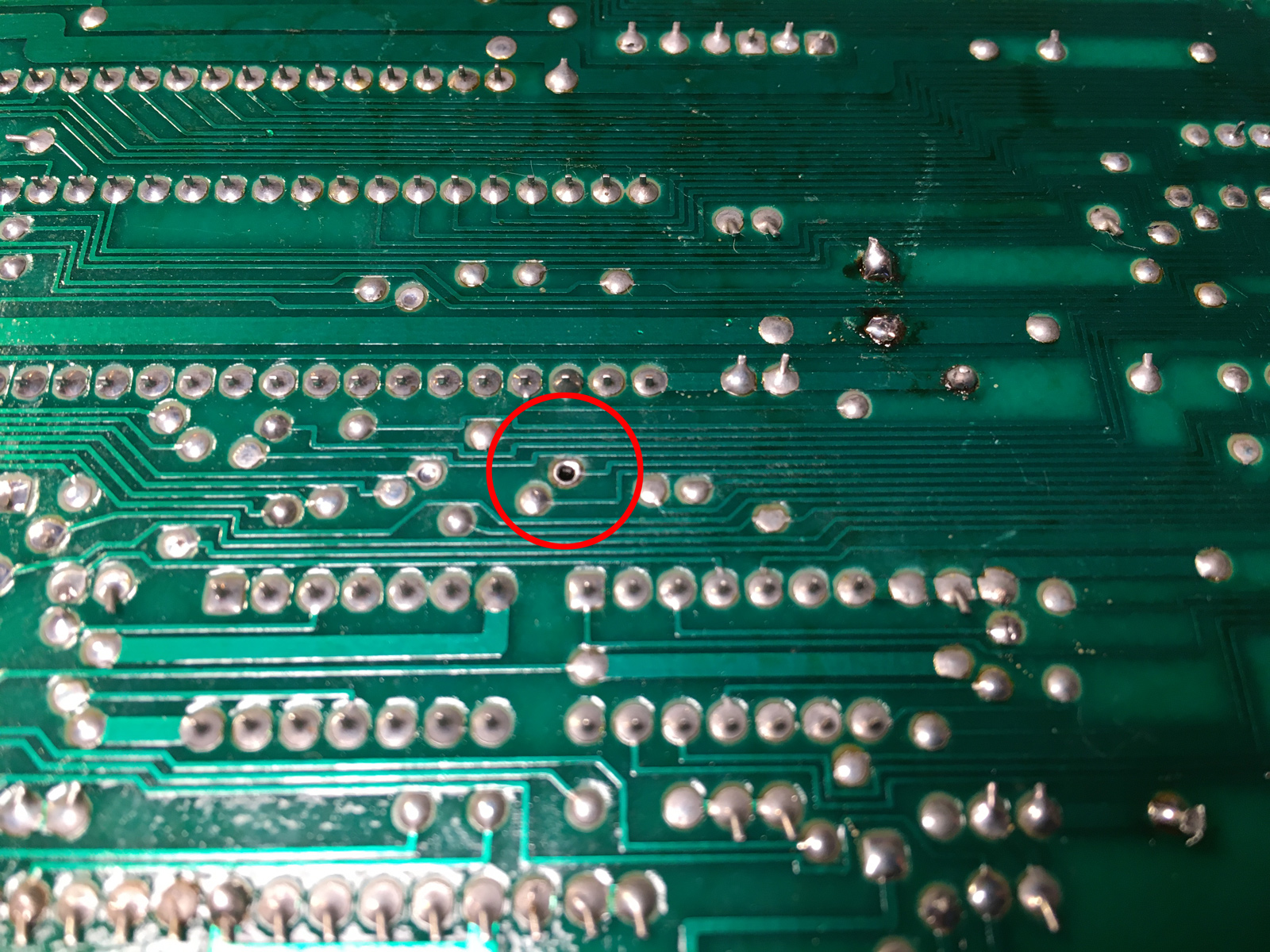
What's on the other side... What the fluffernutter?! The entire trace has been obliterated! What kind of a nincompoop does that? He only needed to clip the leg of the capacitor! $#%!!
26-no-trace-of-it.jpg


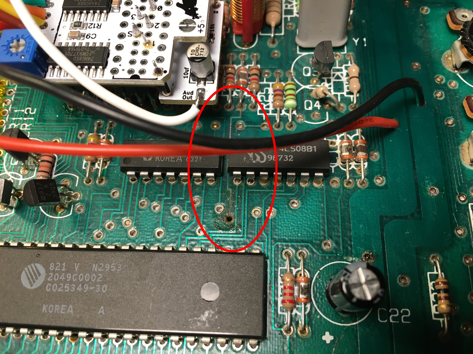
Ugh. Okay, well at least that explains it. So I bridged the missing trace with a purple wire (one of the few colors I haven't used yet):
27-rejoined.jpg


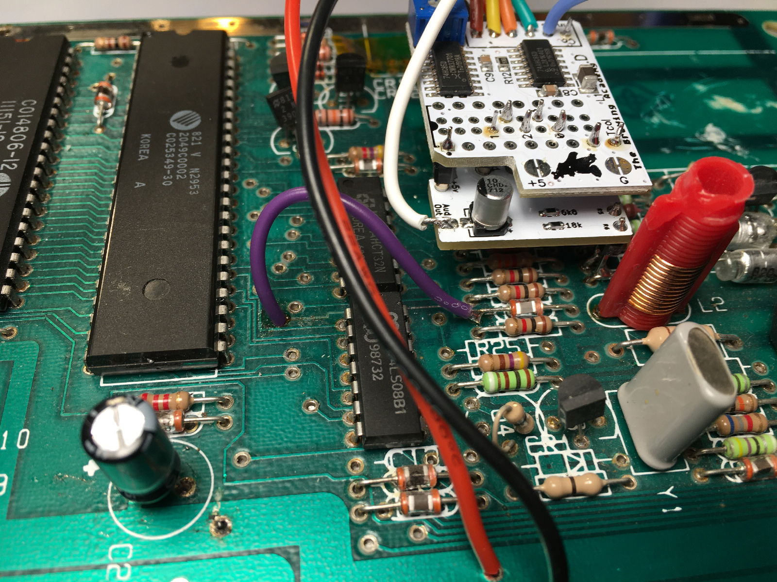
And presto! AAUUGGHH!! What happened?
28-whoopsie.jpg

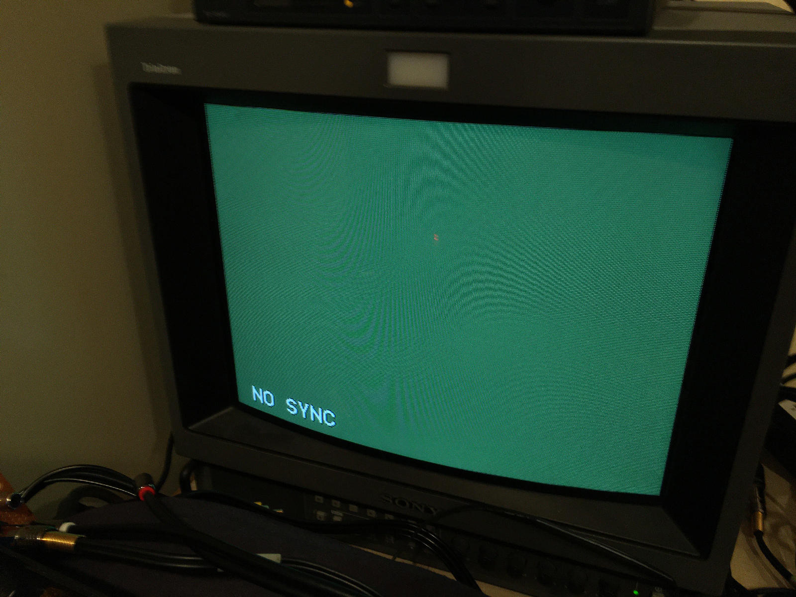
Heh. Forgot to plug in a cart.


Okay. Back to the audio test. Well... Channel 0 works. But nothing from Channel 1. Back to the circuit board.
29-half-a-tia-is-better-than-none.jpg


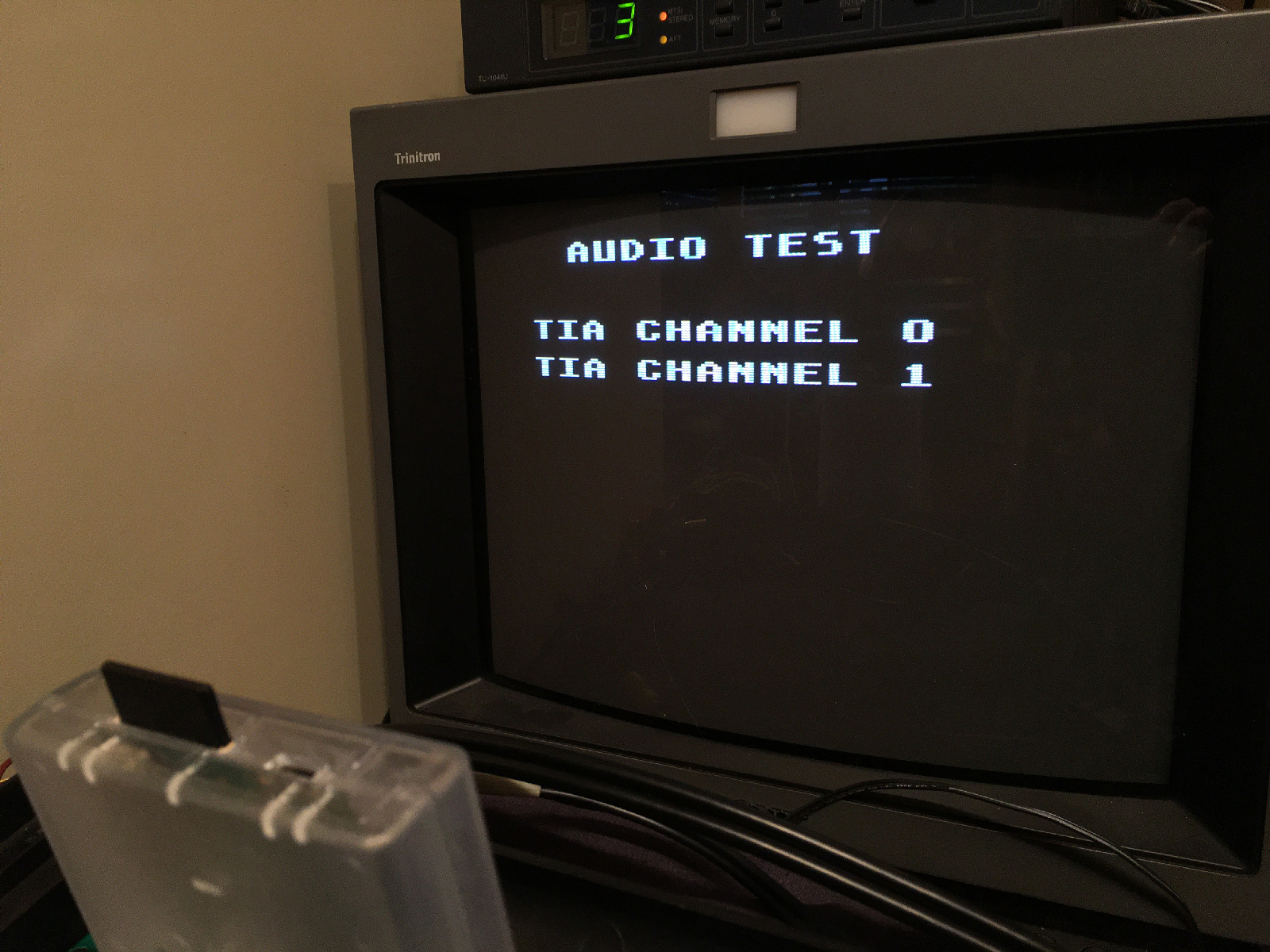
There should be trace joining TIA pins 12 and 13 (there's one on my 7800). But it's not there. There's no continuity. I'm guessing the previous modder cut that trace so the TIA would be "stereo"?? I guess?
30-no-trace-here-either.jpg


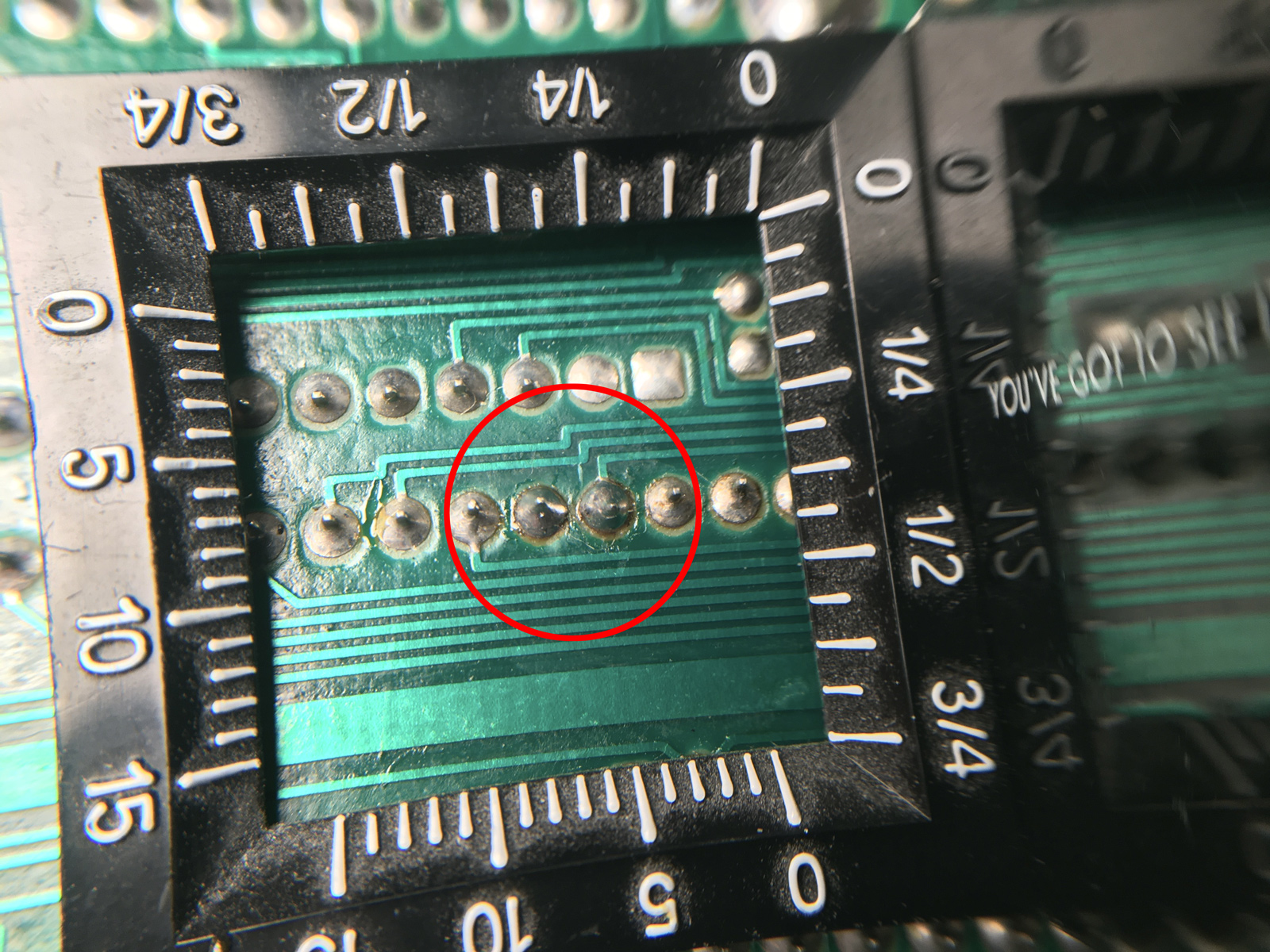
Anyway, I bridged the two pins...
31-retraced.jpg


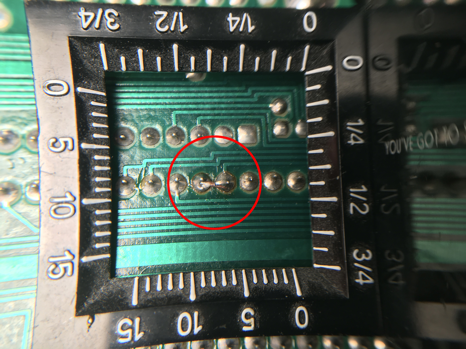
A little further-away look at it:
32-retraced-too.jpg


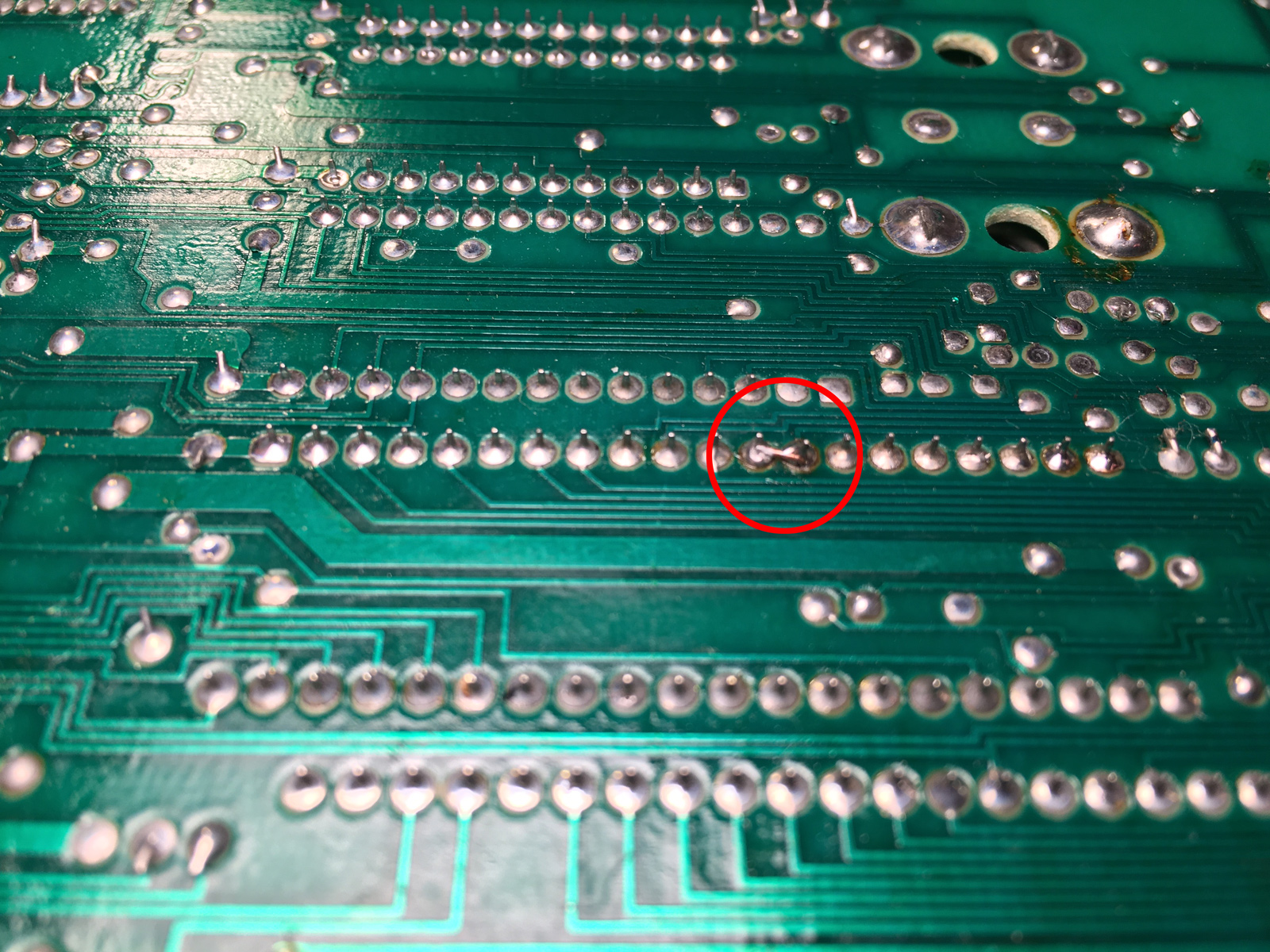
And while I had the soldering iron out, I also re-anchored the power jack. It wasn't sitting flush to the circuit board, and I was concerned about there being too much force exerted on the connection. The plastic tabs which are supposed to hold this in place are loose or missing. Not sure what do do about that... maybe a little epoxy?
33-power-connector.jpg


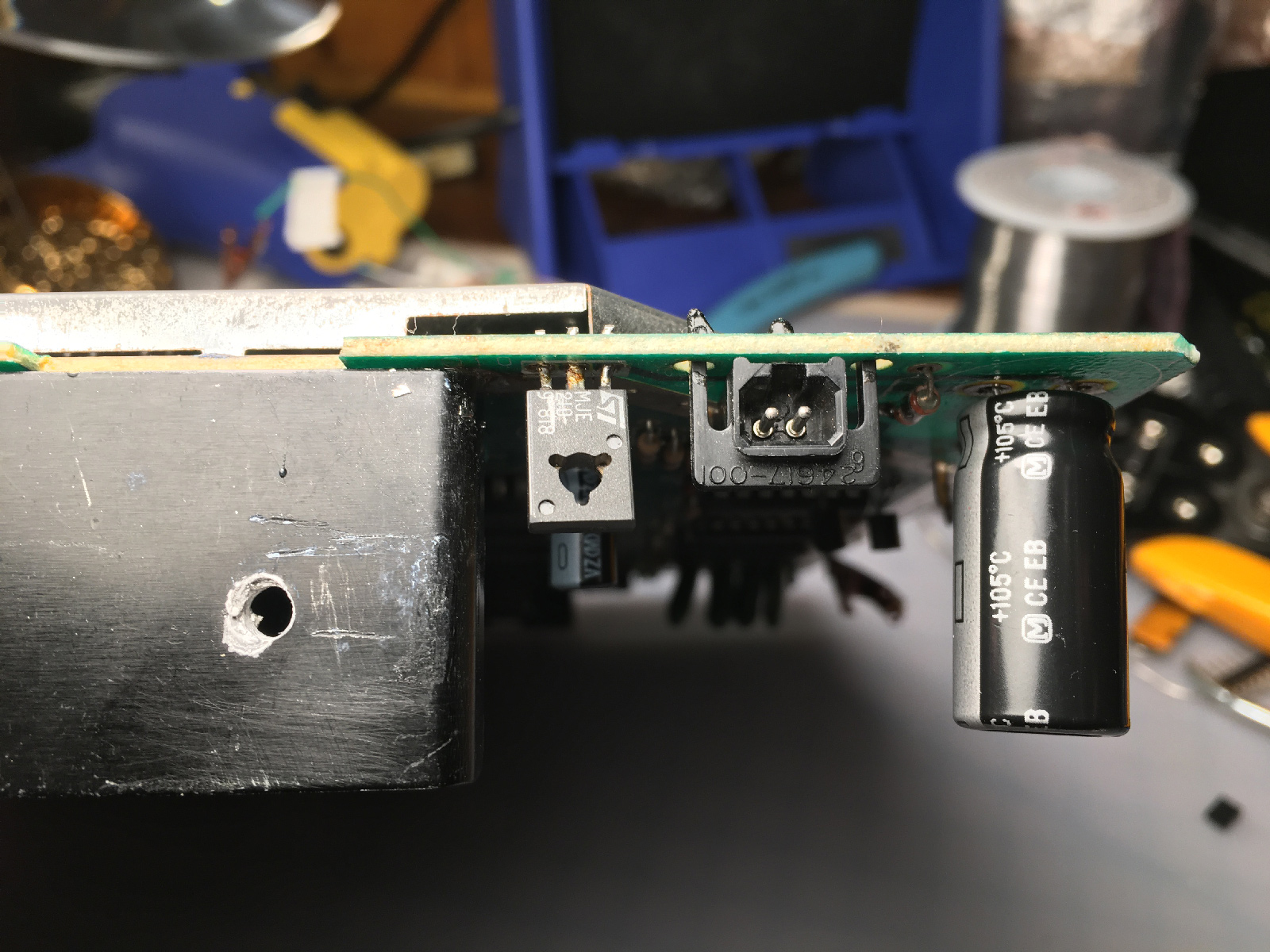
Anyway, back to testing. And this time - full TIA audio! And video!
34-finally-full-tia.jpg


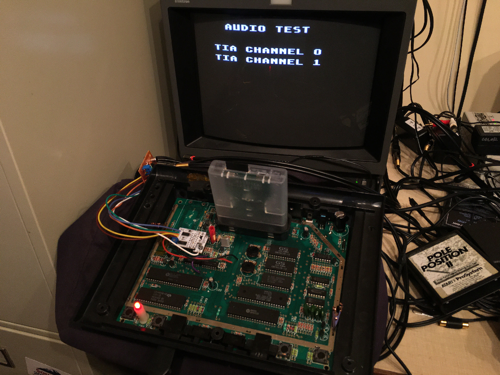
And POKEY audio as well!
35-and-pokey.jpg


After the console warmed up, the colors changed slightly (to be expected):
36-pretty-colors.jpg


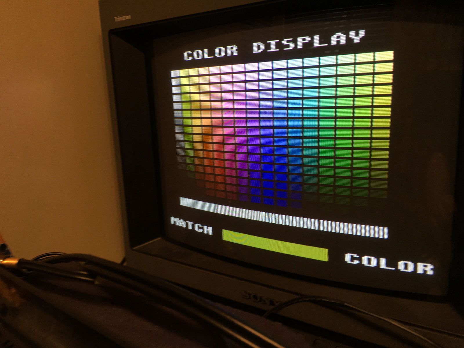
The right side of the bar is now warmer than the left side. Previously, the left side was warmer.
37-should-they-match-or-not.jpg


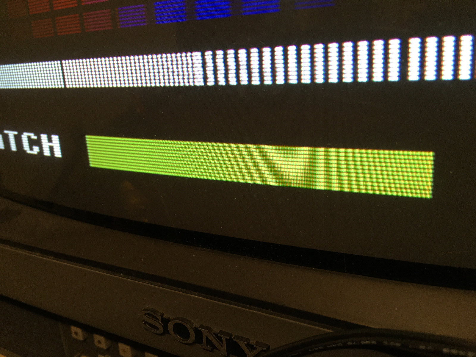
So we're almost there! Now, I just need to fire up Tower Toppler, and adjust the... well... crap.
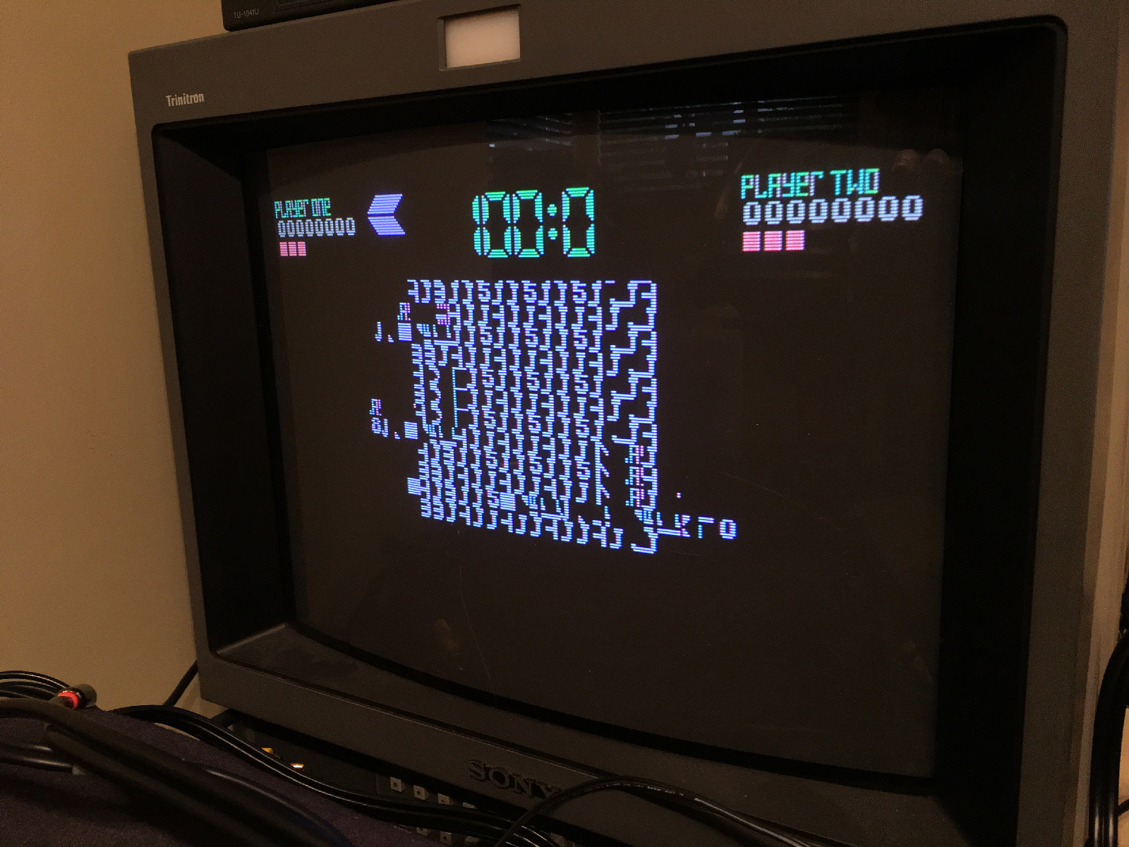
38-tower-toppled.jpg


Eh... who plays Tower Toppler anyway? :P Guess I should report this in the Concerto Firmware thread.


Up next: Final wiring and patching up the case. Then we'll get around to what those switches are for. ;) 


Published 1/16/23, 5:44PM

  • Like 2

6 Comments


Recommended Comments

The audio output pad uses a standard size that comes in the KiCad footprint library actually. But I'm confused on the via spacing comment? They are spaced to match up with the resistors you solder it down onto. The other vias on the top are aligned with the vias on the UAV and those I can't control of course.


Odd about the audio the way it was but yeah, I told you before in PMs that the audio had been done in stereo as I could tell from the old mod that was in place. But didn't know they removed the trace completely as that wasn't needed. Glad you sorted it out and got it corrected though. What's up with Tower Toppler though? Unless that is through a Concerto? I don't think TT is working through the Concerto yet is it?


Link to comment

Oh..to answer about your color bars question.


So..first off with the UAV at least, those bars won't actually match when the rest of the colors are set correctly. You will always have the right bar seem more olive or brown vs the left side. It is the same way with the color bar generator for the 2600. If you do properly match them as you stated, the other colors will look a bit off. So for 2600 games I eyeball the color using Pitfall. But on the 7800 side, what I do is wait for the console to have been on for about 5min and then adjust so that the bars are close but always with a bit more brown/olive on the right side bar vs the left.


Through RF output, it is a different story and you actually do want those to match up. In fact, I usually use the RF for that purpose and then leave it. The UAV will alter some of the tints on the colors and that is just how it is. Again, it was initially designed for the Atari 8-bit computer line and its palette of colors as a result. Changes were made to it so that it could be used on the 2600 and 7800 but there is some tradeoff in the process with color accuracy as a result. 90% of the time it is where it need to be though.


And now I realized you are using a concerto. That 7800 utility actually tests the POKEY too during the audio test. But ONLY if it detects the Pokey. However, as Fred didn't include the RNG on the HOKEY (Which I'm assuming you are using?), it doesn't see the Pokey chip and as a result you are only getting the TIA audio channels on that test. With an actual Pokey installed, it will play the two TIA channels, and then 4 more channels showing Pokey Audio channel 1 - 4. On mine Concerto, that pokey test is absent with my HOKEY. However, with a HOKEY in my old Mateos cart it does work, but doesn't display while playing the tones, they just play on their own.


And...there are some unused vias you can use on the board to test continuity of the connections to the UAV. They are all pretty easy to get to minus the points for Sync and Lum 1 which are covered with components on the board. But the rest of them can be checked in other places. Remind me and I can send you an old diagram I have as I used to wire the UAVs to those alternate points vs along the resistors a few years back.


Link to comment
23 minutes ago, -^CrossBow^- said:

But I'm confused on the via spacing comment? They are spaced to match up with the resistors you solder it down onto. The other vias on the top are aligned with the vias on the UAV and those I can't control of course.

Sorry - I should've been clearer: The UAV jumper vias are what I had the most trouble working with. Bad close-up vision + ham-fisted soldering skillz aren't a great combination for soldering things that are right next to each other.

23 minutes ago, -^CrossBow^- said:

What's up with Tower Toppler though? Unless that is through a Concerto? I don't think TT is working through the Concerto yet is it?

It's through the Concerto. There's a hacked ROM that works with some consoles. It runs on my 7800, but not John's. I'm hoping the next Concerto firmware update addresses it, but there's no final release version of it yet - just interim builds.

Link to comment
5 hours ago, -^CrossBow^- said:

Through RF output, it is a different story and you actually do want those to match up. In fact, I usually use the RF for that purpose and then leave it.

Sadly, not an option with this 7800. :( 

5 hours ago, -^CrossBow^- said:

The UAV will alter some of the tints on the colors and that is just how it is. Again, it was initially designed for the Atari 8-bit computer line and its palette of colors as a result. Changes were made to it so that it could be used on the 2600 and 7800 but there is some tradeoff in the process with color accuracy as a result. 90% of the time it is where it need to be though.

90% for any NTSC device is probably 20% better than normal. :ponder:  :D  

5 hours ago, -^CrossBow^- said:

And now I realized you are using a concerto. That 7800 utility actually tests the POKEY too during the audio test. But ONLY if it detects the Pokey. However, as Fred didn't include the RNG on the HOKEY (Which I'm assuming you are using?), it doesn't see the Pokey chip and as a result you are only getting the TIA audio channels on that test. With an actual Pokey installed, it will play the two TIA channels, and then 4 more channels showing Pokey Audio channel 1 - 4. On mine Concerto, that pokey test is absent with my HOKEY. However, with a HOKEY in my old Mateos cart it does work, but doesn't display while playing the tones, they just play on their own.

I'm using an actual POKEY. RevEng mentioned in the comments there that the issue (in this case) is the header in the ROM file for the Utility Cart needs to be updated, which will be included in Trebor's next ROM pack update.

5 hours ago, -^CrossBow^- said:

And...there are some unused vias you can use on the board to test continuity of the connections to the UAV. They are all pretty easy to get to minus the points for Sync and Lum 1 which are covered with components on the board. But the rest of them can be checked in other places. Remind me and I can send you an old diagram I have as I used to wire the UAVs to those alternate points vs along the resistors a few years back.

Cool - thanks! When I get to my 7800, I'll give you a nudge about it.


Thanks again for all the help in getting this particular one working again - especially for the Mount/Audio/Chroma board. That really simplified the process a great deal. (And thanks to alex_79 as well!)


I'll be modding a couple of 2600's as well, so I'll be able to do a comparison of what it's like to install UAV's in those systems. 

Link to comment

For composite & S-Video color (hue) is determined by the phase of the chroma signal versus the colorburst signal in the horizontal sync at each specific point in time.  On the 2600 & 7800 the way they selected the phase for each pixel is taps off a delay line.  So color 0 is the first tap on the line (no delay, matches colorburst) while color 15 is the last tap on the line.  The "length" of the delay line is set by the resistor (to compensate for slight differences at the gate level).  So if you want to have consistent colors for all 2600s the easiest way is to adjust the resistor so color 0 is the same as color 15.  You lose a color, but it's a quick & easy way to do the job.  OTOH, if you want all 16 colors then you can adjust the resistor so the two are different (which is what most emulators effectively do I believe).


Oh, don't forget that the 7800 has separate resistors for the 2600 TIA and 7800 MARIA.

Edited by EricBall
  • Thanks 1
Link to comment
3 hours ago, EricBall said:

For composite & S-Video color (hue) is determined by the phase of the chroma signal versus the colorburst signal in the horizontal sync at each specific point in time.  On the 2600 & 7800 the way they selected the phase for each pixel is taps off a delay line.  So color 0 is the first tap on the line (no delay, matches colorburst) while color 15 is the last tap on the line.  The "length" of the delay line is set by the resistor (to compensate for slight differences at the gate level).  So if you want to have consistent colors for all 2600s the easiest way is to adjust the resistor so color 0 is the same as color 15.  You lose a color, but it's a quick & easy way to do the job.  OTOH, if you want all 16 colors then you can adjust the resistor so the two are different (which is what most emulators effectively do I believe).

Thanks for writing that up! I remember hearing how color was generated on the Stella at 20 tapes, but couldn't recall exactly where they said it (or what the exact explanation was).

3 hours ago, EricBall said:

Oh, don't forget that the 7800 has separate resistors for the 2600 TIA and 7800 MARIA.

Yep. The 2600 colors look fine, the 7800 colors need to be tweaked a little.

Link to comment
Guest
Add a comment...

×   Pasted as rich text.   Paste as plain text instead

  Only 75 emoji are allowed.

×   Your link has been automatically embedded.   Display as a link instead

×   Your previous content has been restored.   Clear editor

×   You cannot paste images directly. Upload or insert images from URL.

Loading...
  • Recently Browsing   0 members

    • No registered users viewing this page.
×
×
  • Create New...