Jump to content
  • entries
    143
  • comments
    451
  • views
    174,012

Chimera Teaser continued - Ouroboros


mos6507

781 views

Besides using the ARM as a coprocessor, the big feature we're working on are the queues. I'd like to call them Ouroboros but that is kind of a long name. It's hard to get used to it. David Crane calls them "data fetchers". Other people have called them "stacks".


If you aren't a programmer yet or if you are a novice, you might not see the value in these, so I'll try to explain the rationale. There are three big advantages to Ouroboros, speed, simplicity, and compactness.


Let's review the Atari 2600 architecture. The 2600 has been described as a "1D" system because it only has enough registers to draw one scanline at a time. In fact most games rewrite some of these registers in mid-scanline to be able to do more, so it could be seen as even more constrained. Think of the Atari 2600 as a series of brushes that you paint with. The kernel allows you to change the colors and sizes of the brushes as the video beam scans across. How quickly and effectively you can make those changes will make or break your game.


One of the big timesinks in a kernel is the logic involved in knowing when to draw a sprite and how to pull the proper frame of sprite animation data.


Atari engineers realized how tedious it was with the 2600 so when they designed the Atari 400/800, they took the TIA and created a helper chip called ANTIC that would automate the kernel process. The data for the screen would come from zones of RAM. You could finally have real bitmaps. Sprites came from strips of RAM. This wasn't like a PC graphics chip with dedicated RAM. It was still flexible enough that you could rearrange where the graphics data came from, even in the middle of the screen, making for fast animation and other effects.


A similar concept can be applied even with the 2600. All you really need is more RAM. The Supercharger provided that. Imagine a strip of RAM representing the sprite shape across the entire height of the screen. Imagine a strip of RAM representing the color of that shape. The game can erase and redraw the shape up and down the strip to move the sprite up and down. This is the same technique used to move sprites vertically on the Atari 400/800. The difference with the 2600 is that instead of an ANTIC display list, you have a handwritten kernel doing everything manually.


So the inner loop of the kernel to draw a single sprite with Y as the scanline counter might look like this:


LDA SPRITEDATA,Y

STA GRP0

LDA SPRITECOLORDATA,Y

STA COLUP0

STA WSYNC


As you can see, there is no if/then logic. The kernel is very simple, leaving plenty of room for other graphics on the same line.


There are problems with even this approach, though. The Supercharger only gives you 6K to work with. Reserving 100 or 200 bytes per element adds up fast. It also takes precious time during VBLANK to erase and write back in the data into these strips.


Remember that most of the space in these strips would be padded with zeroes. This is fine on the Atari 8-bits. I don't think they shipped with less than 16K RAM in addition to the actual gamecode on ROM carts, but it is very wasteful when you only have 4K available at a time and 6K max for gamecode and data.


By 1984, David Crane, who was intimately familiar with the 2600 and also helped write the Atari 400/800 OS, decided to take what he learned and try to upgrade the VCS with something called the DPC chip in Pitfall II. Unlike the Atari 400/800 approach, these strips of RAM would not be randomly accessible by the VCS. The VCS would only see one byte of data at a time. The cart kept track of an internal index pointer for each queue. Each access would trigger an automatic seek-forward operation. When the cart reached the end of the queue, it would automatically loop back. There were other bells and whistles in the DPC chip, but that was the core of it.


So a DPC kernel might look like this:


LDA SPRITEDATA (aka QUEUE0)

STA GRP0

LDA SPRITECOLORDATA (aka QUEUE1)

STA COLUP0

STA WSYNC


Every read operation has now saved 1 CPU cycle and the cartridge is no longer cluttered with large reserved strips, just a zone of 1-byte access windows or hotspots.


No matter what you do to help out the 2600, no matter how much memory you have, you still have to deal with the critical timing of the kernel itself. I think David Crane really knew what he was doing when he devised the DPC chip. My feeling is that "queues" are indisputably the best way to improve the graphics on the 2600 (let alone sound, if you want to do the Pitfall II approach there too).


Nevertheless, even the DPC architecture is missing something. RAM. Pitfall II still just uses the stock 128 bytes of VCS RAM. The queues can be massaged somewhat at runtime, and some are dynamically generated, but by and large you are talking about read-only resources.


Ouroboros in Chimera are intended to take the DPC idea and add the read-write capability. At first I was envisioning them to be writable only at design-time as part of game loads. You could overwrite them only as part of the multiload process. But we should be able to make them fully read-write at runtime.


I am not a DPC expert, but the patent seems to discuss ways to apply masks to the queues. Let's say a queue had a lot of data in it. The game could tell DPC to only show a subsection of the queue and hide the rest. The kernel would try reading from the entire height of the queue, but will wind up only showing the area it was configured to show, starting at a particular scanline. This largely gets around the read-only limitation. On Chimera, we're talking about potentially having as much as over 64K worth of RAM for queue data. So we're not concerned with optimizing for storage. It makes sense for us to simplify the design instead. So what you put in the queue is what gets displayed. If you don't want it shown, erase it. If you want frames of animation, feel free to precook each frame in its own queue if you don't want to overwrite the queue on each frame. It's simpler, and hopefully more flexible.


Right now we intend to control queues with only two hotspots, a read/write hotspot and a seek control hotspot. We'd also have a handful of "group" seek hotspots so you could do a global or grouped seek. The grouping and the loop-points would be set at design-time.


Since this is a teaser, it's a little too early to go over the Ouroboros system in complete technical detail, but I am happy to announce that we are already successfully running multiple queues on the prototype hardware.


Since no emulators support Chimera right now, nor should they since the hardware is in a state of flux, there isn't much sense sharing the binary of the demo. When run on the Cuttle Cart or an emulator, our most recent demo just displays a solid static playfield since the kernel just reads from fixed ROM addresses. When run on Chimera, however, the game clears and loads up 4 queues which generate two multicolored playfield messages that run vertically on the left and right half of the screen. The left half scrolls up and the right half scrolls down. On the surface it isn't that impressive. You could easily accomplish that effect via Supercharger RAM alone, for instance. But it is a proof of concept. If this works, then all sorts of other things should be possible.


Also, these initial queues store their data directly in the ARM's native RAM. What this means is that the ARM could run specialized functions to write to these queues on its own with full unrestricted throughput. One obvious application of this is for bitmaps. We initially intend to use this feature to build the menuing system of Chimera. Chimera would generate text that looks like Stellar Track automatically internally. The actual kernel would be a lot simpler than Stellar Track. It would simply spool out data directly from the queues and not be concerned about rendering any of the text between rows. So we hope that the VCS-side of the menu application will be incredibly tiny. Also, any game that runs entirely out of a bitmap like Stellasketch or Suicide Mission could just pass the rendering task almost entirely to the ARM between frames. You could imagine the kinds of things that might enable you to do. Maybe going from this:


s_Tempest_1.png


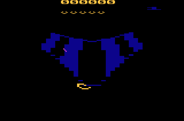
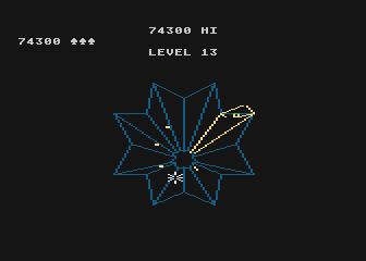
to a little closer to this:


tempest_4.png

11 Comments


Recommended Comments

Certainly there is a lot of potential with an approach such as you describe. The 4A50 has a little bit of clever hardware to assist in EEPROM access, bitmap displays, and certain types of table-based execution, but nothing nearly so complex as the DPC or Chimera.


I'm curious, though: do you see the Chimera as being a static bunch of ARM code that basically just acts like a very fancy but deterministic hardware device, or do you see Chimera programs as having two parts: the 6507 part and the ARM part?


In a sense, it would seem there's really no need for much of anything in the way of intelligence in the 6502 code. You wouldn't even need any real address decoding--A0 and A12 would suffice. Start by holding $7C on the bus. A12 will remain high while A0 repeats the five-cycle pattern low-high-low-low-high. Immediately after the end of a pattern repeat, output "$4C 00 10" and then start outputting load-immediate and store instructions. To read hardware registers (TIA or RIOT), float the bus after outputting a NOP-ZP or NOP-absolute instruction and watch what appears there. Just make sure to spit out "$4C 00 10" at least once every 4096 fetches.


Such a game could push the 2600's hardware to its limits. But it would also no longer really seem like a 2600 game.


Something like my 4A50 banker is certainly designed to be helpful to the CPU, but the 6502 is still responsible for controlling things. If someone had wanted to impliment my 4A50 design in 1983, they could have done so if cost and form factor weren't issues. It would probably require four RAMs and four ROMs, and either a bunch of discrete-logic chips or else a fairly simple custom chip (simpler than the Supercharger, actually). By contrast, neither the ARM chip nor the technology to emulate it discretely really existed in 1983.

Link to comment

The original intention was to make a Supercharger replacement, not to strap a 70mhz CPU to the TIA. The design just happened to evolve to this point. As unlikely as it seems, this appears to be the most economical solution. So we've made the determination to go for broke with the ARM rather than waste it as a glorified I/O chip. Doing this doesn't really increase costs that much.


So unless the ARM drops out of the design, which doesn't seem likely, then I really see Chimera as a platform on top of a platform like the Sega 32X, much moreso than the Supercharger is. On the surface it is a Supercharger replacement with built-in flash. All the extra functionality is "latent". Standalone Chimeras will offer it up for new development, but if a Supercharger homebrew ships on a Chimera cart, it won't take advantage of those features. Nevertheless, the features will still be there in case the cart's programmability is unlocked. Technically every cart, Standalone or embedded, will build out an effective userbase of compatible players/devsystems for Chimera-native games.


If people never use all of the new features, I'm fine with that. But they will be there.


The Supercharger designers never knew that it would be used as a homebrewing device decades down the road. So I'm thinking equally long-term. Long after Chimeras are being made anymore people might be tinkering with them. So I think it's worth adding "cool" features that might intrigue people.


It will be possible to code in different ways for it depending on how aggressively you want to use the ARM. It's not going to enforce any one style. I do not see the ARM completely taking over the VCS. I don't think the timing allows for that. I think that went away when we added the CPLDs back in.


I've tried to work it out so that there is just enough resources in the cart to give the VCS a serious shot in the arm, but without increasing the overhead much. It's still a byproduct of the design, not the be-all-end-all. I'm going to keep the thing at a low pricepoint and any overage is coming out of my pocketbook so that enforces some restraint :evil:


As a consequence of thinking economically, the ARM is going to have some constraints of its own. It will only have 8K of internal RAM, 4K of which devoted to queues. It will have slow access to SRAM. It will have to do most of its processing during VBLANK. Limited if any multitasking. During the kernel it will be busy indexing queues. Somewhere it will wedge in serial handling. It can not directly read the VCS hardware registers or any of zero-page. So there is still a whole other set of challenges to try to overcome.


It would probably not be such a waste of someone's time to learn how to code for an ARM chip. This chip isn't that different from one of the chips in the GP2X.

Link to comment

I'm curious, though: do you see the Chimera as being a static bunch of ARM code that basically just acts like a very fancy but deterministic hardware device, or do you see Chimera programs as having two parts: the 6507 part and the ARM part?

When I first thought of hooking the ARM to the 6507, I wanted the 6507 to be a slave to the ARM. All it would do is transact with zero page for the ARM. The 6507 kernel would really just read display information the the ARM supplied it. I wanted to do this mainly for my benefit though, not really as something to offer to others. But the Chimera design has now taken on a much larger purpose and scope, but has managed to keep the same price point, so much more focus needs to be applied to usability, from a normal gamer, a programmer, and a hardware add on designer standpoints.


For the gamer stand point, we are making the hardware transparent. Loading games and playing games will require, at most, a knowledge of how to connect the cart to a serial or USB port and running simple PC/Mac applications.


From the programmer side, and to answer your question, programming the ARM will not be necessary. The ARM will come with many features that can be enabled via 6507 software. So queues for example, to use them your code has to simply turn them on and access the correct locations. Same with serial ports, if you dont want them, just dont use them, but they will be there if needed. If you want to use the ARM to do very specific things, you will have to write software for the ARM and the 6507. Your custom ARM code should be loadable with your 6507 game code, via multiloads, or loading through a hotspot during run time, hopefully. The intention is that there will not be a need to do anything other than load one binary to the cart and play. I planned on providing hooks into the ARM so programmers would just need to focus on their specific code, and not the whole of the ARM code.


As for hardware developers, we hope to have two serial ports available, one will be at logic levels and the other will be at RS232 levels, both should have hardware flow control if needed (other ports may also be offer, but nothing concrete). The data from either of these ports will be passed through the ARM to the VCS without manipulation (if you want the ARM to process the data, you will have to write ARM code). So if Richard was interested in making a version of his AtariVox to connect to the serial port, he would only need to make sure that the voltage levels matched the port, and provide some VCS code to drive it. The advantage to our serial ports is that they communicate in bytes, not bits, this should save some kernel time when dealing with external devices.


When we finish, we hope to have a simple to use device, but still be super flexible from a design stand point. Since all the code, schematics, protocols, CPLD designs, and tool chains (all tools used in development of the cart are available for free) will be available, a motivated developer should be able to push the performance boundaries of hardware and software without much effort.


Vern

Link to comment

What I found when doing Leprechaun is although I could read both players and playfield from SC-RAM, I didn't have really enough time every frame to BLIT the player graphics from ROM to SC-RAM. This wasn't a problem for the mostly static playfield. My final solution was to use more traditional (zp),y addressing and just store the pointers in SC-RAM, which could be copied into normal RAM as part of the repositioning logic.


I've often felt it should be possible to duplicate parts of the DPC design using modern CPLDs, the 3 channel music driver in particular.

Link to comment

A DPC would probably have to be an expensive FPGA with little room for anything else, otherwise we would have seen it on the Cuttle Cart 2 but maybe I'll be proven wrong. Using the ARM as the data fetcher doesn't sound like a lot of work to do but I guess it must eliminate a lot of custom logic, hence saving money.


I haven't looked at a disassembly of Pitfall II (if there is one) but in order to do the 3 channel music it's necessary to write to one of the audio channels once a scanline including overscan/VBLANK.


I would think that this would put a serious crimp on coding the game logic during VBLANK since you will have to keep stopping what you are doing to write to the audio register once every 76 cycles.


Maybe someone could explain how Pitfall II manages to work around that better.


Technically, the ARM could generate waveforms on the fly, but I was thinking it might be simpler to create tiny looped samples offline and just populate queues with them. So every note and every chord combination would have its own queue. Then the VCS would sequence through these combinations. Since it would not be necessary to seek to subsections within these samples then if 256 bytes per sample is too small we may be able to have larger ones configured on game-load. You'd still be able to rewind the samples and they would still loop at the end but you wouldn't be able to random-access beyond index 0-255.


That's not the only way to do it, of course. You could have a frame-based music sequencer where the music data streams in from the queues. The music data could have a queue for each audio register so instead of dealing with samples you are back to 2-channel audio but with almost no memory footprint to drive it.


The combination of RAM and queues in and of itself opens up a tremendous amount of possibilities without even using the ARM to run custom coprocessing functions.

Link to comment
I haven't looked at a disassembly of Pitfall II (if there is one) but in order to do the 3 channel music it's necessary to write to one of the audio channels once a scanline including overscan/VBLANK.


I would think that this would put a serious crimp on coding the game logic during VBLANK since you will have to keep stopping what you are doing to write to the audio register once every 76 cycles.


Maybe someone could explain how Pitfall II manages to work around that better.

I just took a quick look at the Pitfall II code (AFAIK there is no commented disassembly) and it looks to me like yes, they do write to AUDV0 every 76 cycles or so. However...it looks like there is a lot of leeway built in, though. Most of the time the writes happen soon after WSYNC, but there are a few spots that look like this:

LF93A: LDA	$1006   
   STA	AUDV0   
   LDA	INTIM   
   BNE	LF93A   

That makes me think that perhaps the Pitfall II queue only changes about every 76 cycles, or...?

Possibly - that would give a ~7.6 kHz Nyquist rate, which is generally acceptable for digital sound.


Regardless, I'm guessing that $1006 does not access a queue, but maybe a simple DSP. Does anyone know?

Link to comment

It's all in the DPC patent if you have the patience to read through it and the mind to understand the technobabble style.


http://www.freepatentsonline.com/4644495.html


I noticed that there are really only 8 queues active at a time on the DPC but they are highly alterable at runtime. The 64 fetchers really just provide various filtered ways of looking at the same underlying data. It would be nice to know when those filtered views were actually used in the game. Bit shifting and reversals I think would be useful for playfields.


Because Chimera will provide 64K of SRAM and 4K of ARM RAM for queues, we're planning to offer 200 SRAM queues and 16 ARM queues. So there is less of a need for runtime controls.


The patent does talk about ways it allows you to write to hotspots. I wonder how similar that is to Supercat's idea.


	  TABLE 1
______________________________________
Data Fetcher Commands
Address Description
______________________________________
$.0..0..0.-$.0.3F
		"Read" Commands
$.0..0..0.-$.0..0.3
		Random number generator
$.0..0.4-$.0..0.5
		Sound value, MOVAMT value AND'd with
		Draw Line Carry; with Draw Line Add
$.0..0.6-$.0..0.7
		Sound value, MOVAMT value AND'd with
		Draw Line Carry; without Draw Line Add
$.0..0.8
		DF.0. display data
$.0..0.9
		DF1 display data
$.0..0.A
		DF2 display data
$.0..0.B
		DF3 display data
$.0..0.C
		DF4 display data
$.0..0.D
		DF5 display data
$.0..0.E
		DF6 display data
$/.0.F  DF7 display data
$.0.1.0.
		DF.0. display data AND'd w/flag
$.0.11  DF1 display data AND'd w/flag
$.0.12  DF2 display data AND'd w/flag
$.0.13  DF3 display data AND'd w/flag
$.0.14  DF4 display data AND'd w/flag
$.0.15  DF5 display data AND'd w/flag
$.0.16  DF6 display data AND'd w/flag
$.0.17  DF7 display data AND'd w/flag
$.0.18  DF.0. display data AND'd w/flag, nibbles swapped
$.0.19  DF1 display data AND'd w/flag, nibbles swapped
$.0.1A  DF2 display data AND'd w/flag, nibbles swapped
$.0.1B  DF3 display data AND'd w/flag, nibbles swapped
$.0.1C  DF4 display data AND'd w/flag, nibbles swapped
$.0.1D  DF5 display data AND'd w/flag, nibbles swapped
$.0.1E  DF6 display data AND'd w/flag, nibbles swapped
$.0.1F  DF7 display data AND'd w/flag, nibbles swapped
$.0.2.0.
		DF.0. display data AND'd w/flag, byte reversed
$.0.21  DF1 display data AND'd w/flag, byte reversed
$.0.22  DF2 display data AND'd w/flag, byte reversed
$.0.23  DF3 display data AND'd w/flag, byte reversed
$.0.24  DF4 display data AND'd w/flag, byte reversed
$.0.25  DF5 display data AND'd w/flag, byte reversed
$.0.26  DF6 display data AND'd w/flag, byte reversed
$.0.27  DF7 display data AND'd w/flag, byte reversed
$.0.28  DF.0. display data AND'd w/flag, rotated right
$.0.29  DF1 display data AND'd w/flag, rotated right
$.0.2A  DF2 display data AND'd w/flag, rotated right
$.0.2B  DF3 display data AND'd w/flag, rotated right
$.0.2C  DF4 display data AND'd w/flag, rotated right
$.0.2D  DF5 display data AND'd w/flag, rotated right
$.0.2E  DF6 display data AND'd w/flag, rotated right
$.0.2F  DF7 display data AND'd w/flag, rotated right
$.0.3.0.
		DF.0. display data AND'd w/flag, rotated left
$.0.31  DF1 display data AND'd w/flag, rotated left
$.0.32  DF2 display data AND'd w/flag, rotated left
$.0.33  DF3 display data AND'd w/flag, rotated left
$.0.34  DF4 display data AND'd w/flag, rotated left
$.0.35  DF5 display data AND'd w/flag, rotated left
$.0.36  DF6 display data AND'd w/flag, rotated left
$.0.37  DF7 display data AND'd w/flag, rotated left
$.0.38  DF.0. flag
$.0.39  DF1 flag
$.0.3A  DF2 flag
$.0.3B  DF3 flag
$.0.3C  DF4 flag
$.0.3D  DF5 flag
$.0.3E  DF6 flag
$.0.3F  DF7 flag
$.0.4.0.-$.0.7F
		"Write" Commands
$.0.4.0.
		DF.0. top count
$.0.41  DF1 top count
$.0.42  DF2 top count
$.0.43  DF3 top count
$.0.44  DF4 top count
$.0.45  DF5 top count
$.0.46  DF6 top count
$.0.47  DF7 top count
$.0.48  DF.0. bottom count
$.0.49  DF1 bottom count
$.0.4A  DF2 bottom count
$.0.4B  DF3 bottom count
$.0.4C  DF4 bottom count
$.0.4D  DF5 bottom count
$.0.4E  DF6 bottom count
$.0.4F  DF7 bottom count
$.0.5.0.
		DF.0. counter low
$.0.51  DF1 counter low
$.0.52  DF2 counter low
$.0.53  DF3 counter low
$.0.54  DF4 counter low
$.0.55  DF5 counter low
$.0.56  DF6 counter low
$.0.57  DF7 counter low
$.0.58  DF.0. counter high
$.0.59  DF1 counter high
$.0.5A  DF2 counter high
$.0.5B  DF3 counter high
$.0.5C  DF4 counter high AND draw line enable
$.0.5D  DF5 counter high AND music enable
$.0.5E  DF6 counter high AND music enable
$.0.5F  DF7 counter high AND music enable
$.0.6.0.-$.0.67
		Draw Line Movement Value (MOVAMT)
$.0.68-$.0.6F
		Not Used
$.0.7.0.-$.0.77
		Random Number Generator Reset
$.0.78-$.0.7F
		Not Used

Link to comment

IIRC the audio portion of the DPC is basically three free running oscillators. So as long as you sample the state on a regular basis (i.e. every WSYNC during active screen and every so often during VLBANK) it shouldn't sound too bad to your ear.

Link to comment

IIRC the audio portion of the DPC is basically three free running oscillators. So as long as you sample the state on a regular basis (i.e. every WSYNC during active screen and every so often during VLBANK) it shouldn't sound too bad to your ear.

If it is something as simple as this, we could recreate this with the Chimera with PWMs or just straight timers. Any idea what frequencies the oscillators run at?


Vern

Link to comment

I know this is only mildly on-topic, so I apologize in advance if you don't like it, but just looking through Pitfall II code I found this interesting bit:

	   LDA	$1006   
   STA	AUDV0   
   LDA	$1006   
   STA	AUDV0   
   LDA	$1006   
   STA	AUDV0   
   STA	WSYNC   

Link to comment
Guest
Add a comment...

×   Pasted as rich text.   Paste as plain text instead

  Only 75 emoji are allowed.

×   Your link has been automatically embedded.   Display as a link instead

×   Your previous content has been restored.   Clear editor

×   You cannot paste images directly. Upload or insert images from URL.

Loading...
  • Recently Browsing   0 members

    • No registered users viewing this page.
×
×
  • Create New...