

2600 Chewnyor Fixit & Mod kit - pt. 2
Entry posted by Nathan Strum in 2600 repair
403 views
So, it's time to throw a UAV mod into this 2600 Jr.
As far as installing mods, this isn't exactly my first rodeo. But it is my first time installing a mod into a Jr., and it's my first time installing a UAV mod into a 2600.
When I installed a UAV mod in John's 7800, I had the advantage of using an auxiliary board from -^CrossBow^- that served as both an audio board and a mount for the UAV. This made installation pretty simple.
For the Jr., though, the UAV instructions warn:
QuoteThis is one of the more difficult installs. There just isn't much room in the 2600jr and removing the 4050 isn't an option as it's used by the reset circuit. Soldering and de-soldering are required.
So that wasn't encouraging. And even though it looks like there may be plenty of space with the RF shield removed, I'll be putting the shield back since one of the goals here is to keep RF output intact:
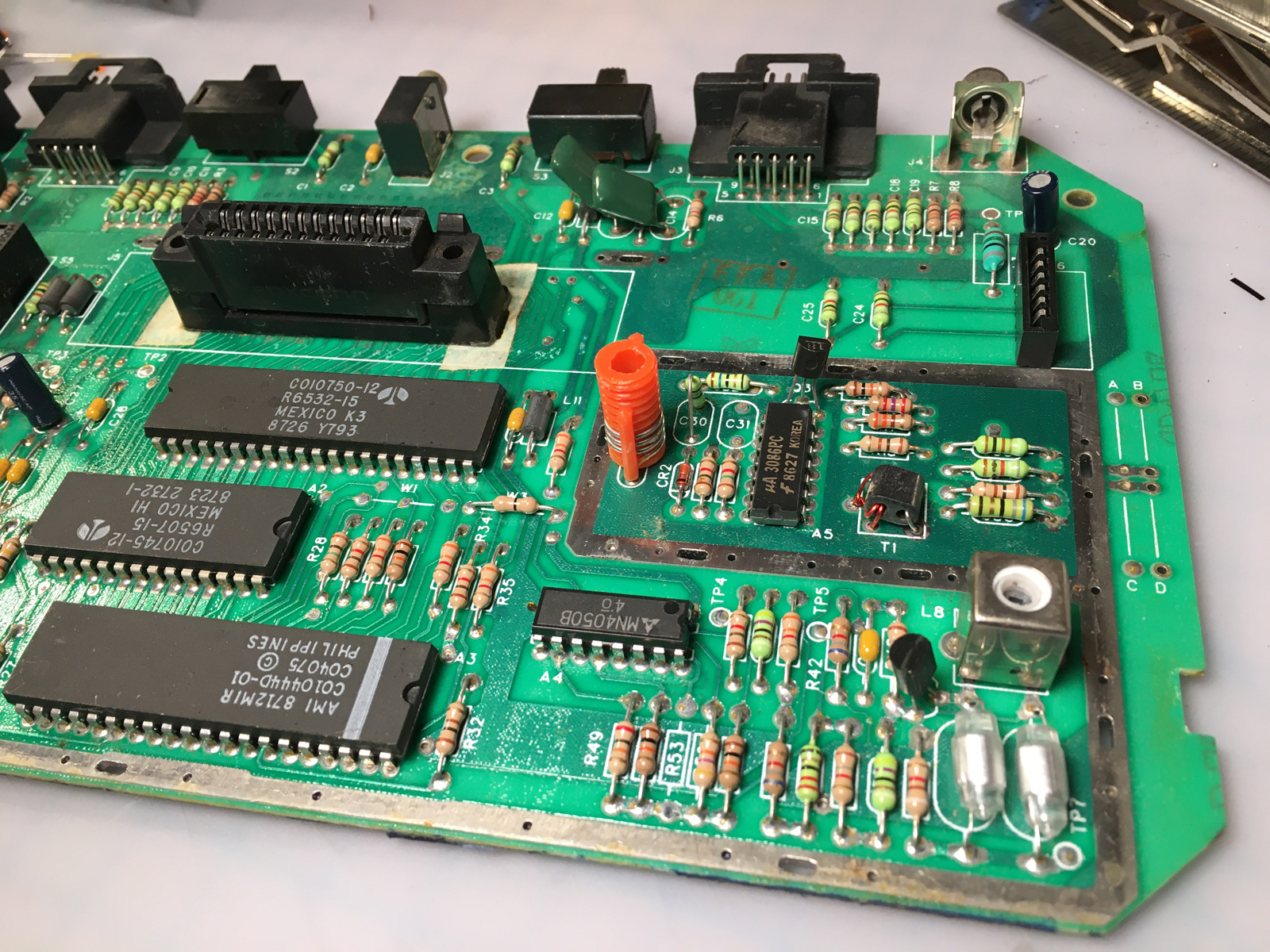
For one thing, John requested it. It's important for developers to be able to see what their games look like with RF, because that's the standard for the system. Some graphical elements can look radically different (or even disappear entirely) in RF that might otherwise look fine on a modded system or in emulation. Besides that, whenever possible, I like to make these mods reversible. It's possible the mod may fail at some point, or a better mod may be developed, or the console fails and the mod needs to be moved to another system. Whatever the reason, it's just good practice. (I couldn't make the mod fully reversible with John's 7800, because a previous modder gutted the RF modulator. But it is still removable by desoldering the resistors it's attached to from the console, then desoldering each resistor from the mod, then reinstalling the resistors back in the console.)
Another warning that comes in the UAV instructions is this one:
QuoteThis manual is a beginning at a collection of all of installation materials created by Bryan and many other AtariAge users over the years on how to install a UAV into an Atari 400/800/XL/XE/XEL/XLD machine (shortened hereafter as “A8 machines”) or Atari 2600s, 5200s, & 7800s!
This is especially true of the Jr. installation. Which reads, in part:
QuoteTo install the UAV, you're going to need to remove the 4050 or run wires to it and mount it outside the shield (which can be done with a Basic Board). These instructions deal with installing it under the shield.
So, there are no instructions for the Jr. for the alternate "outside the shield" installation method. Which is unfortunate, since that's the method I'll be using.
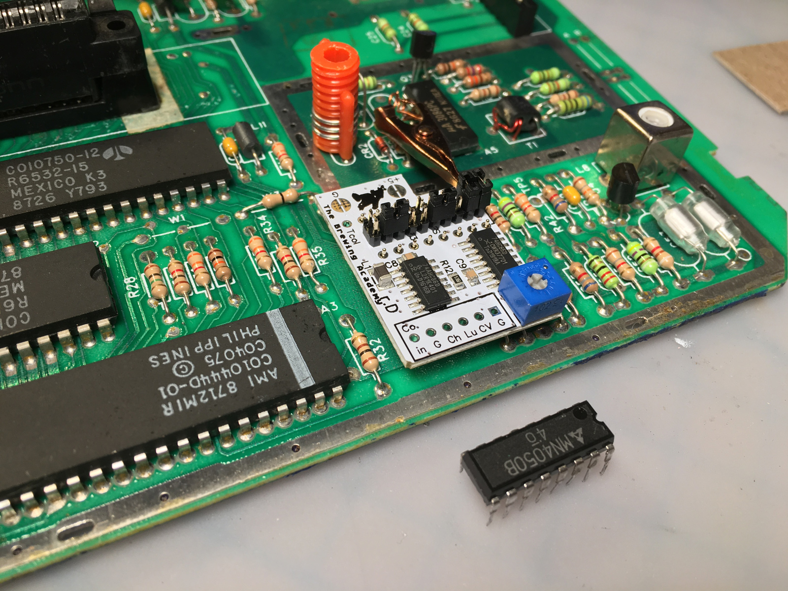
The detault instructions call for removing the CD4050, and installing the UAV mod in its place. Initially, I had considered doing this, so I desoldered the CD4050: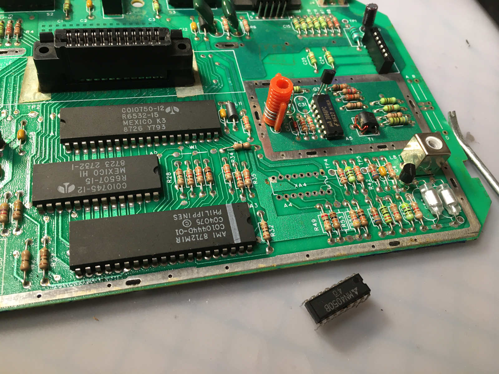
I'm going to pause here for a moment, and interject a mini-rant I have about their instructions for doing this, which read:
Quote2. Desolder the 4050.
a. This can most easily done by clipping the legs off and then clearing the pad holes individually.
Uh... no.
First, I disagree about this being easier. It may seem quicker, but you still have to clear all of the solder and clipped-off legs from each hole. You have to desolder them anyway.
Desoldering is not that hard, and you can pick up a perfectly effective desoldering iron for cheap on Amazon. I used that Radio Shack model for over 20 years (at work and at home), before finally upgrading to the Hakko one I have now. The big difference between the two? The Hakko has a temperature control and a trigger to actuate the vacuum. Otherwise, they essentially do the same thing: melt solder, and suck it up. (And honestly, the Radio Shack one is more fun to use because to clear it, you squeeze the bulb really hard and it blows hot molten solder everywhere!)
If you're going to desolder any components, just buy one. Get the cheap Radio Shack model - you don't need anything fancy. Then just practice on some old throwaway electronics until you get the hang of it. It will make your life easier, and your projects much more enjoyable. You also won't have to destroy components to remove them. And while CD4050s are still in production and readily available, other components are not. And why waste money having to re-buy components if you don't have to?
So... end of mini-rant. Back to the default install.
The UAV mod kit comes with standoffs that mount the board to where the CD4050 was, and jumpers to configure it for the particular system you're installing it in. It's important to remember: this was not originally designed for the 2600. This was designed for the Atari 8-bit computers, and then adapted to work with the 2600 later. Consequently, there are some compromises with it.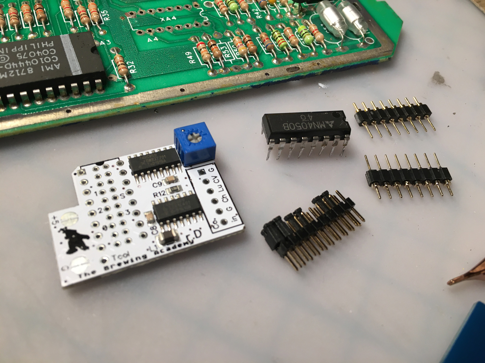
One such compromise, is that in the case of the Jr., the CD4050 has to go back in because the Jr. won't work properly without it. For the default installation, the instructions read:
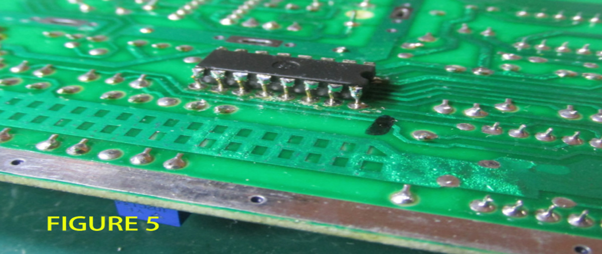
Quote4. Install the 4050 on the bottom of the board (Fig.5).This part is tricky.
a. Trim the leads flush with the bottom of the IC and place in the middle of the UAV pins.
b. The 4050 must be upside down, and pin 1 must be oriented toward the middle of the PCB.
c. It may be necessary to bend the UAV pins slightly outwards.
d. Solder each pin carefully and make sure nothing will contact the bottom shield (if used).
Did you follow all of that? This might help:
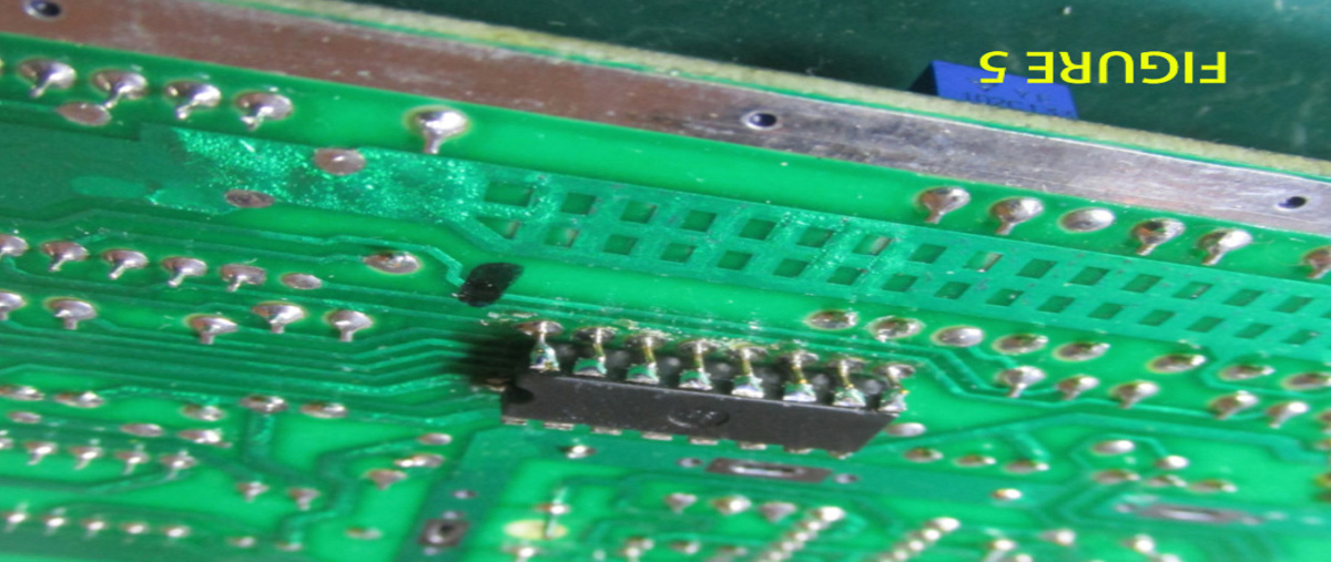
So now you're looking up, at the underside of the board, and the underside of the CD4050, with the UAV mod mounted on the top.
Incidentally, "Figure 5", and the accompanying instructions, are wrong. I'll admit to not trying it, but pin 1 is at the opposite corner of where it should be. Maybe it still magically works. Somehow.
In short, you chop the pins off the CD4050, and install it on the underside of the Jr.'s circuit board, in the exact same orientation it was in originally, by soldering it to the UAV pins that stick through the holes on the bottom. Basically, you're sandwiching the Jr.'s board between the UAV on top, and the CD4050 underneath.
Also, you put a bunch of jumpers in there, that aren't documented in the manual. (Oh, it shows you which jumpers to install... but it doesn't tell you what each one does.)
It was at this point I decided I wasn't going to install the mod this way. For one thing, it's not easily reversible (especially because you have to mangle the CD4050), but also it doesn't address another major shortcoming with the UAV mod: no audio.
While using the CD4050's location seems like a tidy solution for installation, you're still going to have wires running to and from it, and you're going to have to install a separate audio mod somewhere anyway.
The audio board sold as a companion to the UAV has no such provision for convenient mounting. It doesn't attach to the UAV (which would've been nice), it wasn't incorporated into the UAV (which would have been nicer), and the instructions provide no insight on where you might actually locate it inside the Jr.
So I decided to go with the non-default (and undocumented) Jr. installation method, leaving the CD4050 intact, and instead running wires to the UAV mod outside the RF shield. This is actually a common installation method shown in the manual for several other systems. I just had to decipher what was going on, and adapt it to the Jr.
And, of course, find some place to put it. And the audio board.
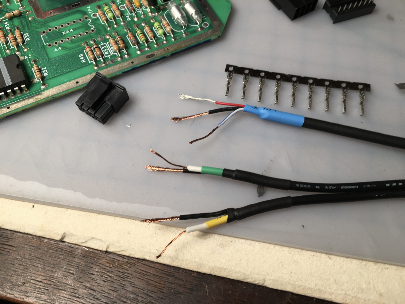
First though, I needed to remove the connector pins from the audio board. They were just going to get in the way, since I wanted to solder straight to the vias instead. So, off came the shrink tubing (and the adhesive gunk inside it):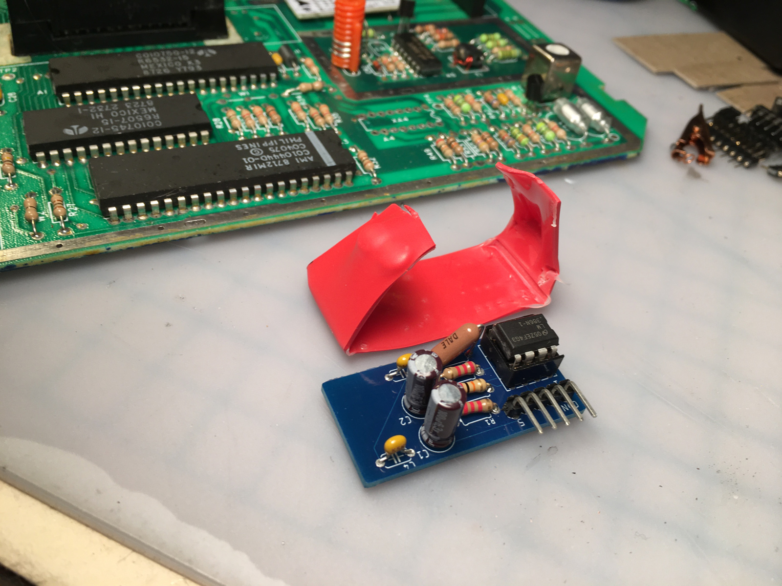
And off came the pins (desoldered... not clipped):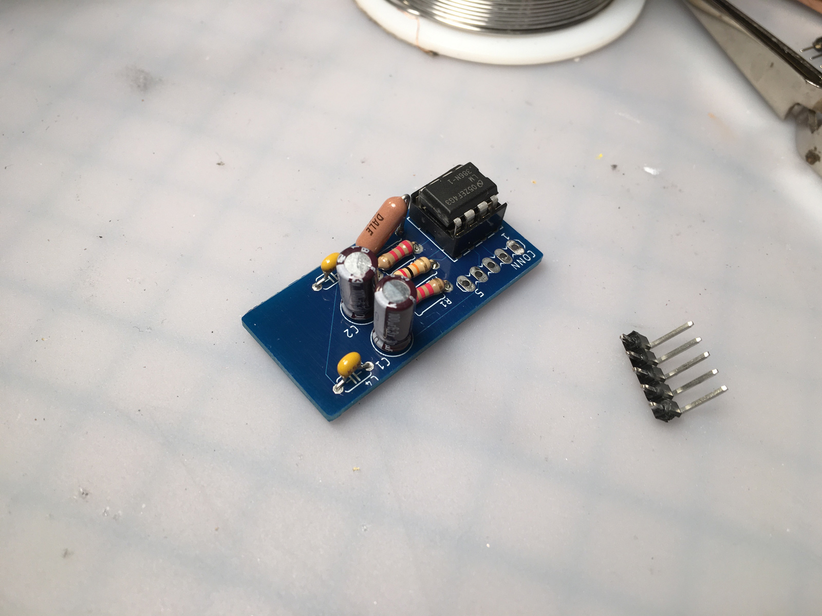
One nice touch - they listed what each connector is for on the underside. Not sure if that's why the board has so much wasted space though. They could've made it significantly smaller just by relocating one component. Still - documentation!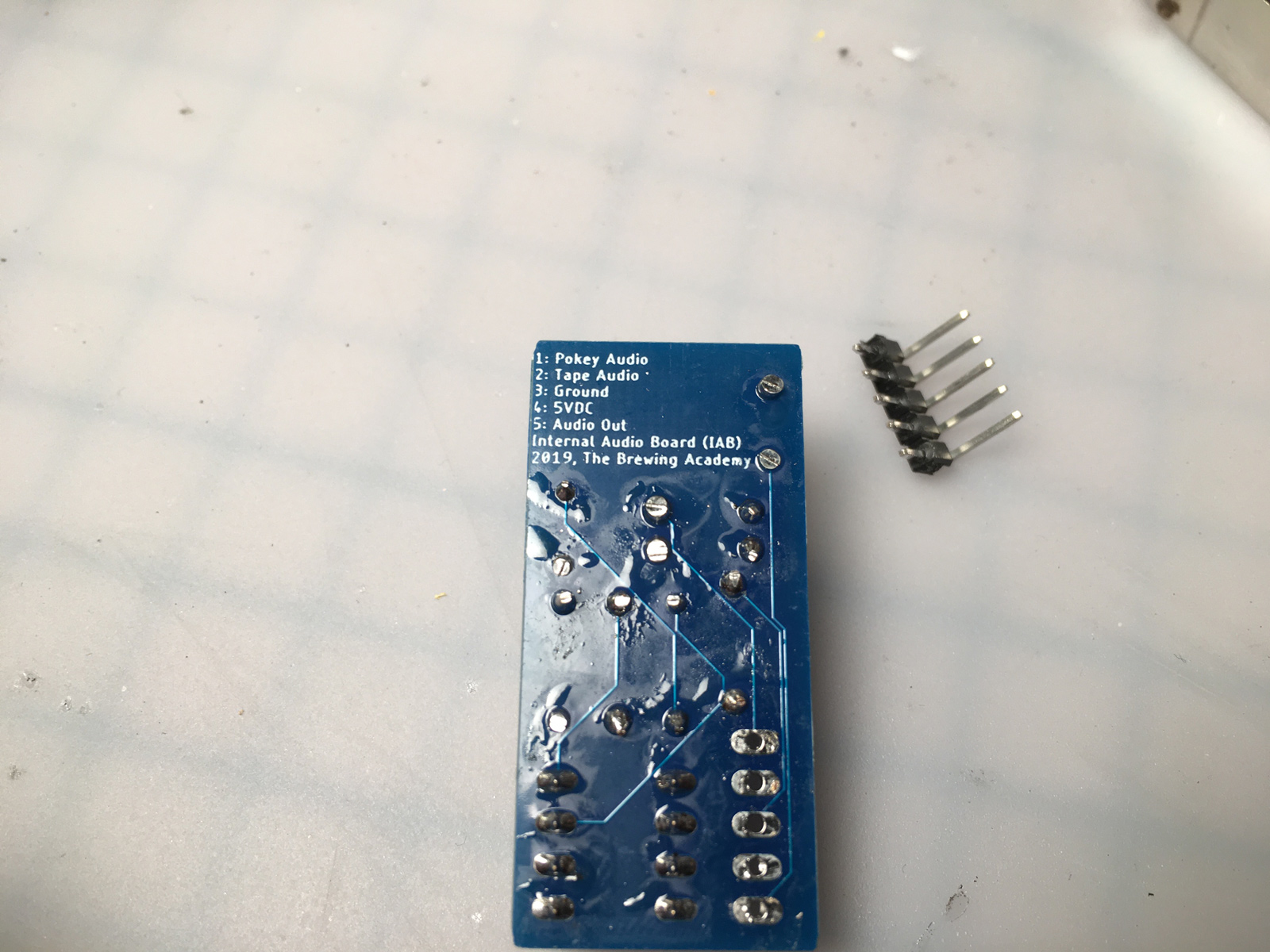
Anyway... so the question is: where to put the two mod boards? One solution would be to put them inside the RF shielding somewhere, and stick them down on top of other components using double-stick tape. This appears to be a pretty common installation method for the UAV mod in other systems. But after having cleaned off someone else's double-stick gunk from the inside of John's 7800 (and having cleaned off a lifetime's worth of double-stick tape in my day job), I decided I didn't want to do that. Reversibility, remember? Double-stick tape is great stuff. Removing it, is not.
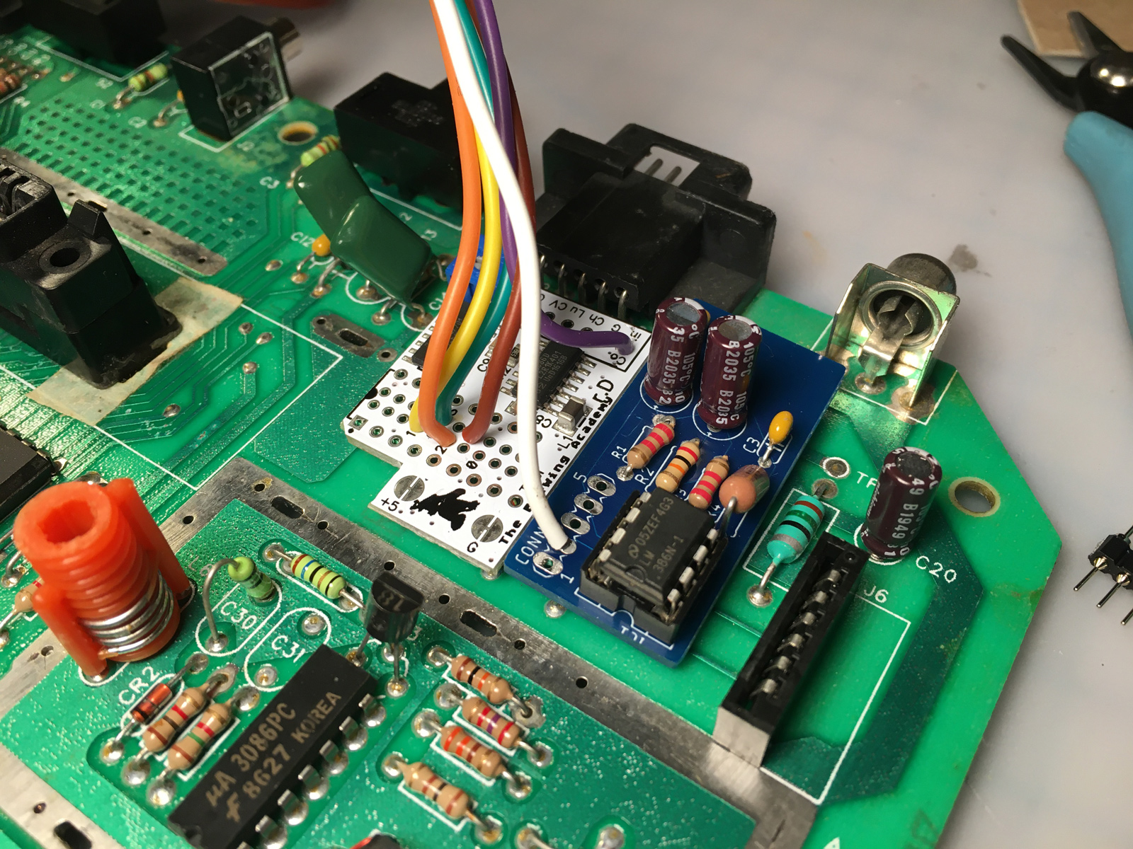
So I put the mods in what turns out is a pretty-much perfect spot. Next to the ribbon connector on the main board, just in front of the player 2 joystick port and RF out jack. They just fit, and there are only a couple of rows of resistors underneath them: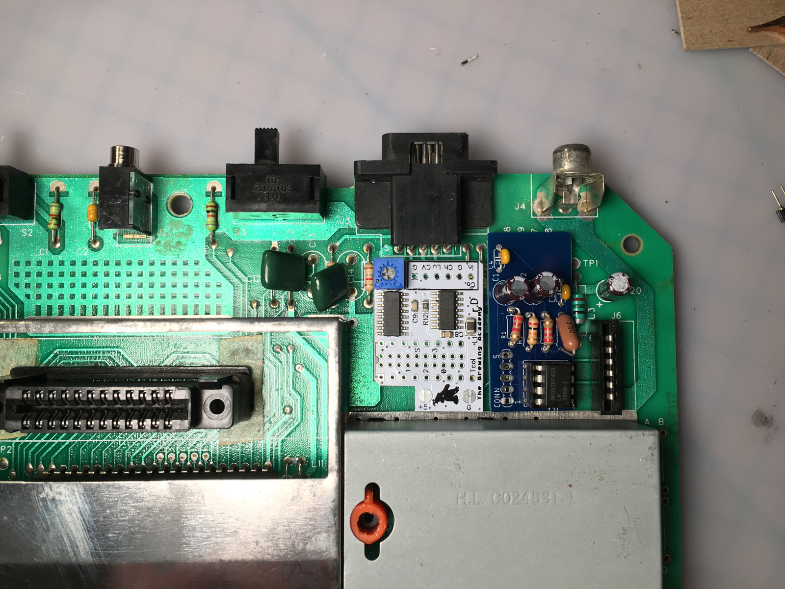
My initial thought was to make a couple of standoffs out of scrap plastic, then attach those to the main board and mods using (wait for it...) double-stick tape. ![]() But the tape wouldn't touch any components, and be pretty easy to remove.
But the tape wouldn't touch any components, and be pretty easy to remove.
Before I got to that point though, I needed to figure out how to route the cables from inside the RF shield. There were a couple of nice gaps in the shield near the cartridge slot that I could feed the wires through: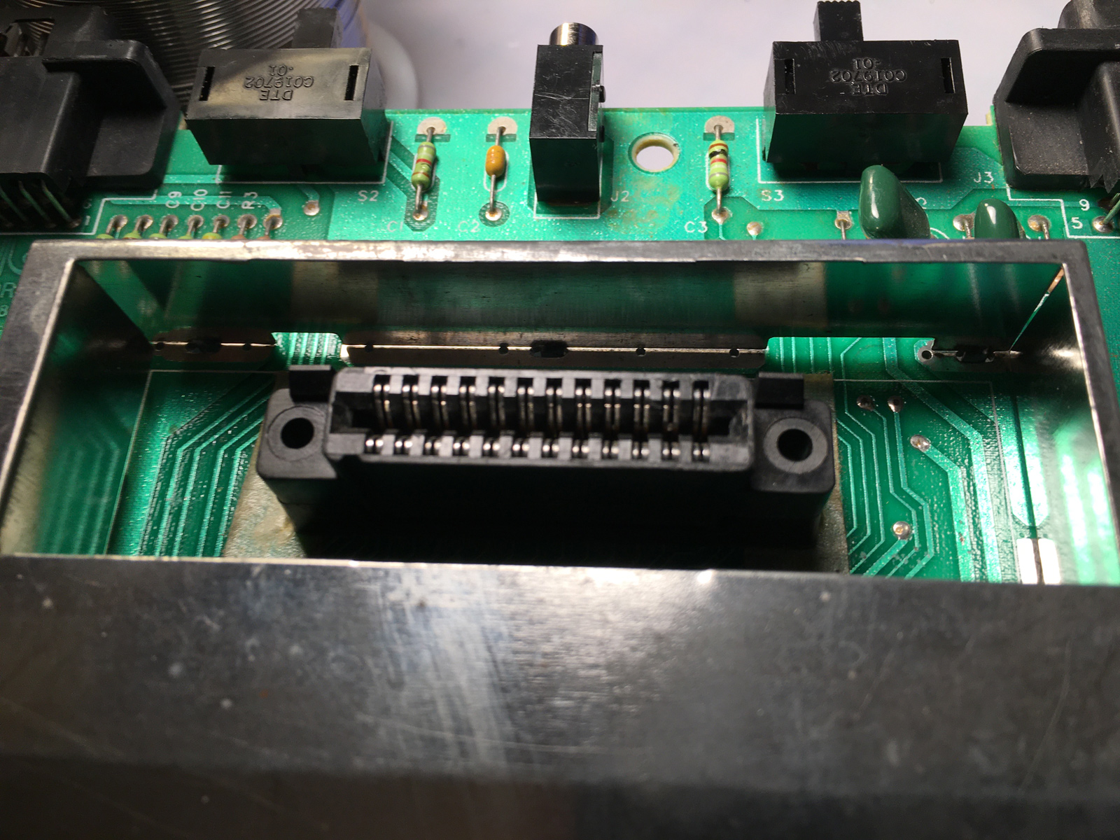
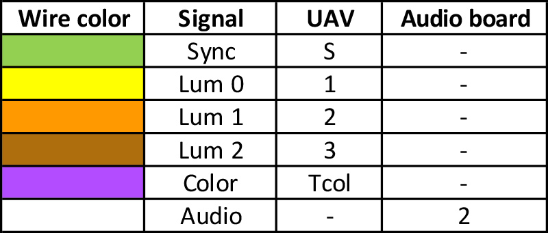
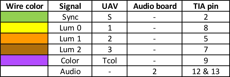
So I soldered on (most of) the wires going into the UAV and audio boards. Here's a handy chart (your wire color may vary):
Then, I test-routed the cables where I wanted them to go...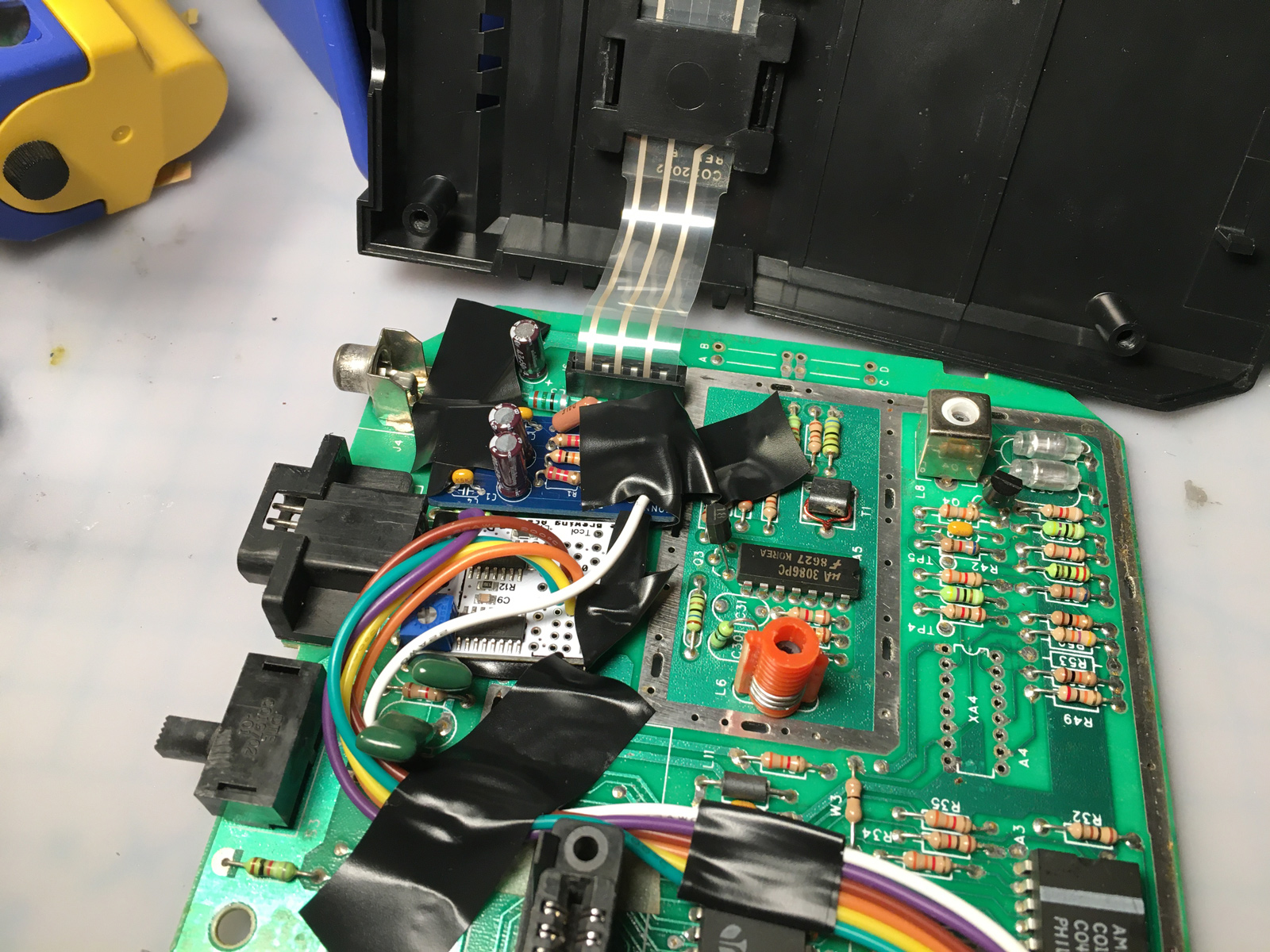
And promptly realized that the plastic cartridge slot was going to get in the way, because it sits flat on top of the Jr.'s main board, and blocks those access points: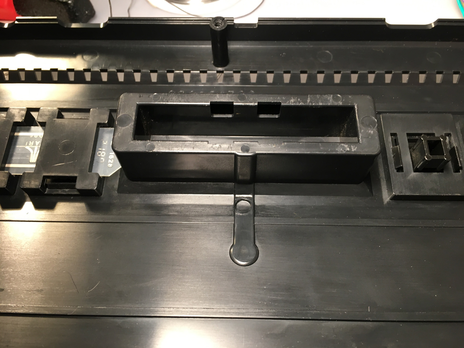
Okay, take two. Run it around the cartridge slot to the other side...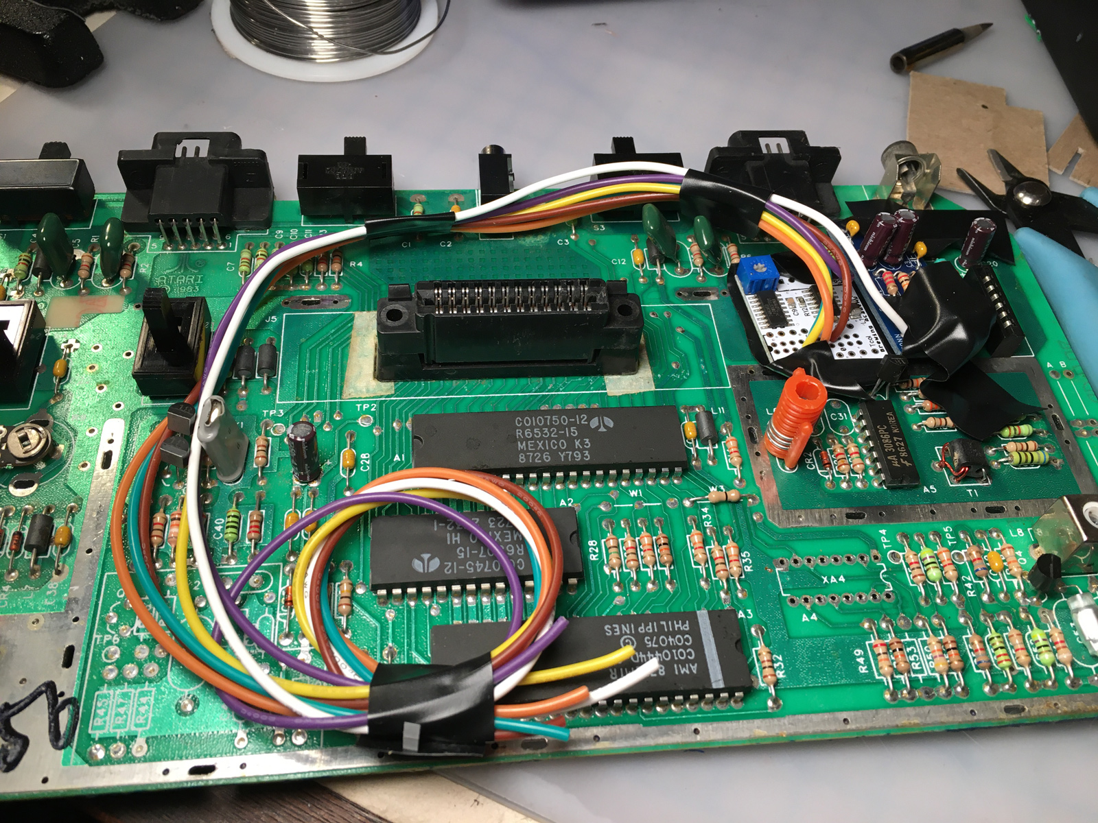
Where there are also gaps underneath the RF shield: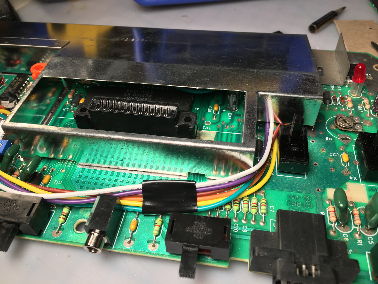
Then, I had a slightly better idea... I noticed a vertical gap at the inside corner that offered more clearance from nearby components: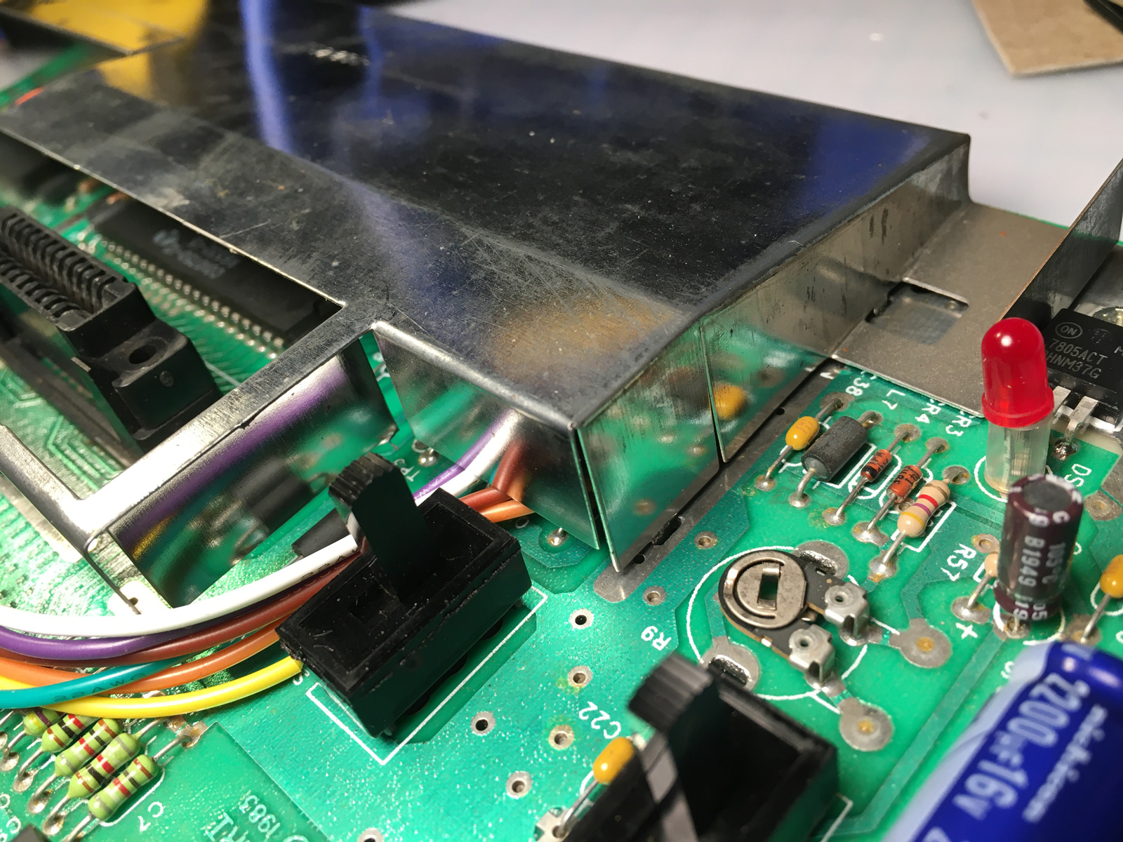
I just needed to add a little electrical tape to soften the sharp edges: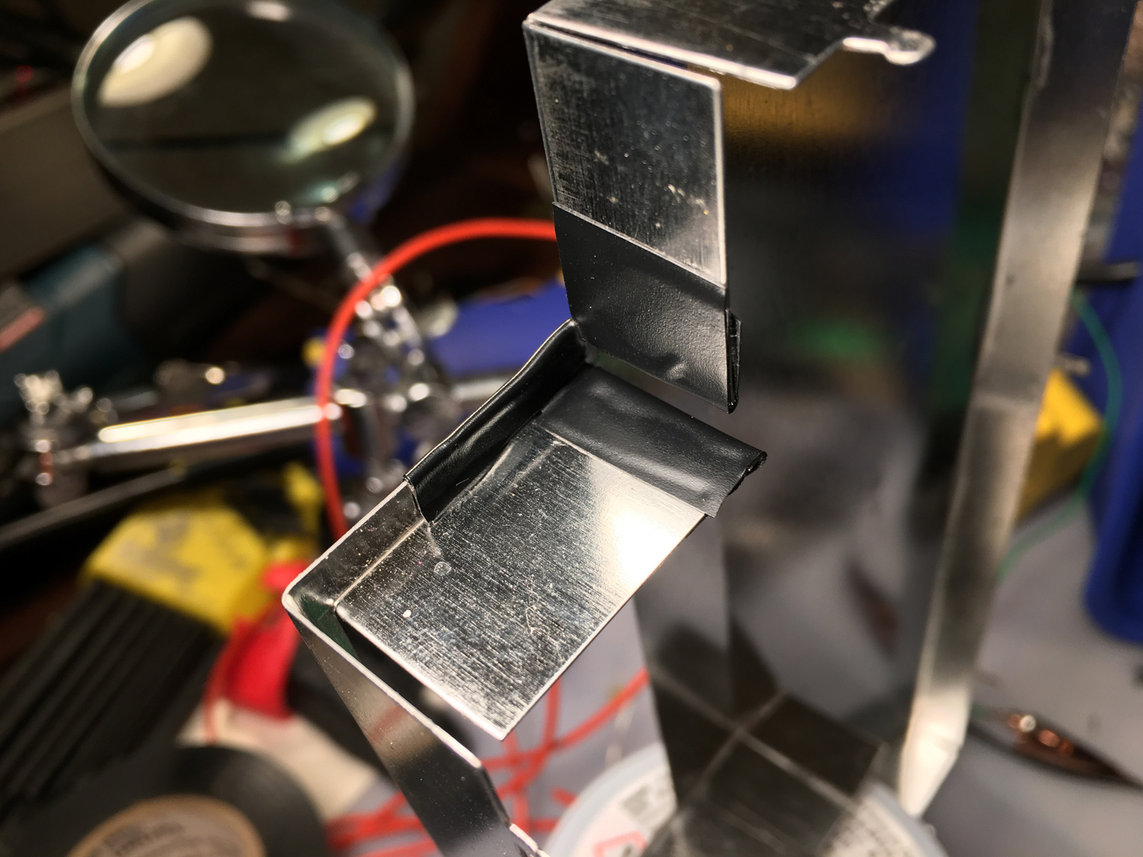
And do some more test fitting: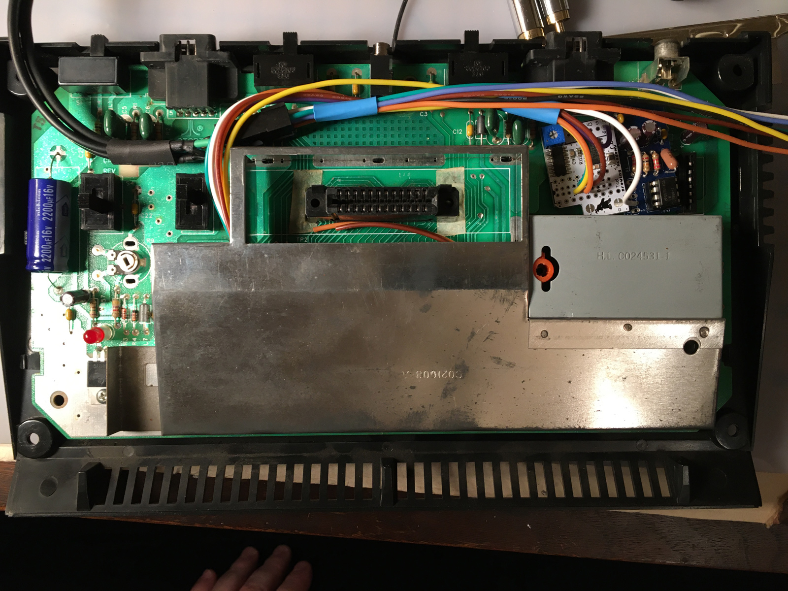
You'll notice the other set of wires draped across the Jr. in the above photo. Those are in-progress output wires.
I'm making those wires pretty-much identical to what I made for the 7800 mod, using a Molex connector to join the S-Video and composite+audio cables to the internal wiring coming from the UAV mod.
Strictly speaking, this wasn't really necessary with the Jr. For other consoles, I use the Molex connector to make disassembly of the console easier. Unplug-and-play, so to speak. ![]() But with the Jr., I added them anyway because I like making more work for myself, I guess.
But with the Jr., I added them anyway because I like making more work for myself, I guess. ![]() Also, this gives me more flexibility in which wires I use where. So we'll go with that.
Also, this gives me more flexibility in which wires I use where. So we'll go with that.
At this point, I was just making sure there was enough room in the Jr. to fit everything in. Success!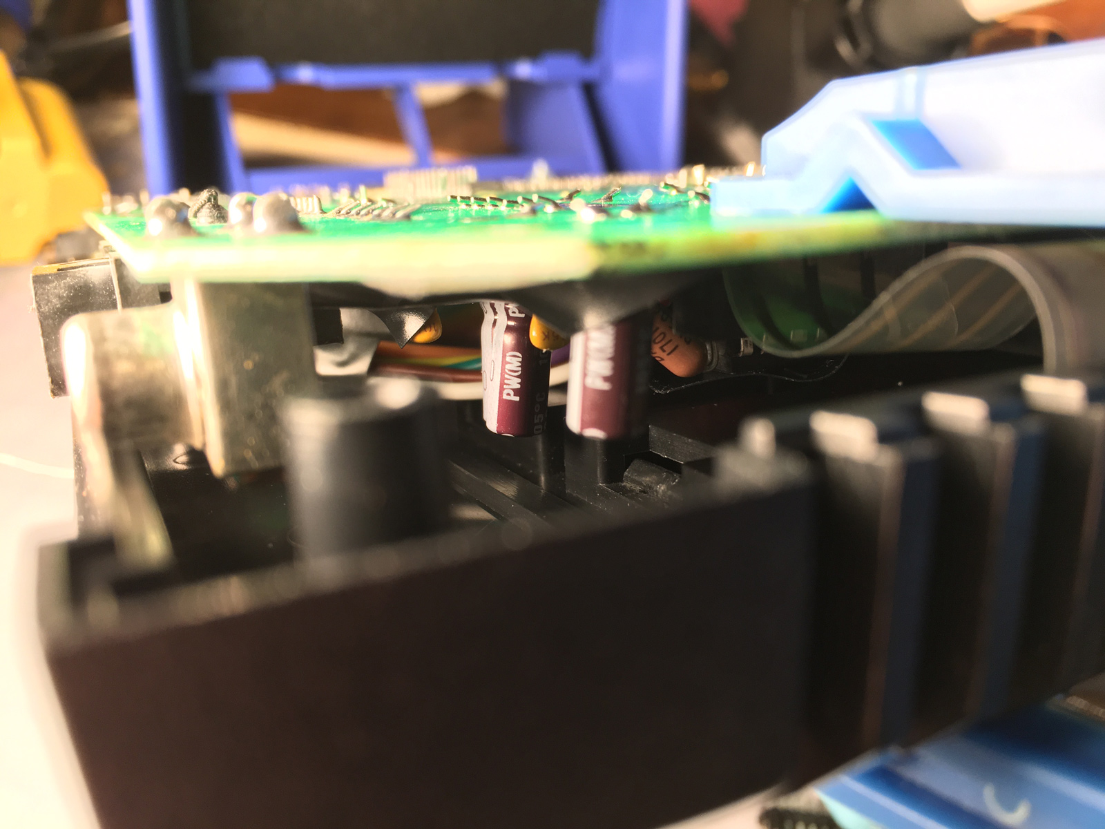
I also updated my wiring diagram to include the polarity markings on the S-Video cable that I use, and the Molex pinouts: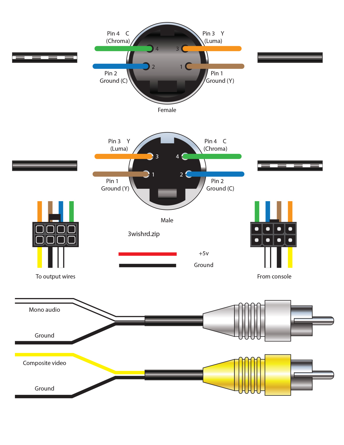
When you get old, it helps to write everything down. Pictures are even better.
Okay, so the wiring will fit. The mods will fit. Now... where do I hook all this stuff up?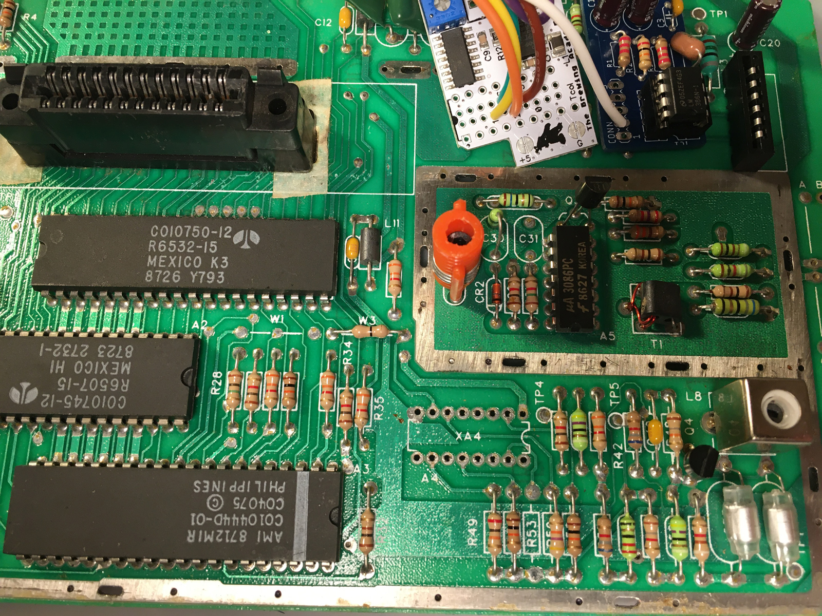
Unfortunately, the UAV instructions are of almost zero help with the Jr. There are some photos showing where to connect wires for a six-switch and four-switch mod, but not a Jr.
It's at this point this blog entry will devolve into another mini-rant. This time, about graphic design. Feel free to skip ahead if you'd like.
On the plus side, the UAV mod comes with a printed version of the installation instructions. I really appreciate that, since I like having printed instructions to refer to, and I don't have to go back to my computer, or have an iPad nearby just to look up a step. I'm old like that. On the negative side, besides the definitely work-in-progress nature of the instructions, is how it was printed. The printed version comes on standard, 8.5" x 11" (US Letter) paper, folded in half. That's great - it results in a nice sized (5.5" x 8.5") manual, and is very cost-effective to produce. The problem is, they made no effort to fit the content to the paper size. It appears the digital version was created first, with no consideration given to how it would be printed, then they just took the digital version, and copy/pasted it as-is into the middle of a 5.5" x 8.5" document, without adjusting the layout, margins, photos, text, or making any changes to improve legibility or clarity. Consequently, you end up with a manual printed on 5.5" x 8.5" paper, that only takes up the middle 4" x 5.5". The resultant oversized margins are just wasted space. The photos especially could've benefited from being printed larger, and it would've made the text far more readable as well. Ideally, the manual would've been laid out for print from the get-go, and then exported as a PDF for a digital version. As it is, while I liked having the physical manual to refer to, I often just left the digital version open on my computer so I could better see it. (You can download both the digital and "for print" versions of the manual here.)
Anyway...
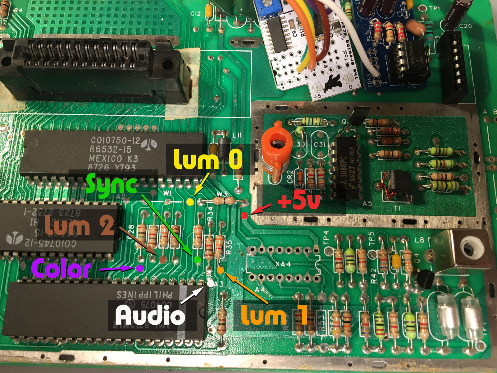
So without instructions for how I wanted to install the mod, a little detective work was in order. First, let's update my chart a little bit to include the TIA:
Now, lets find out where those are on the TIA itself (thanks to various online shematics):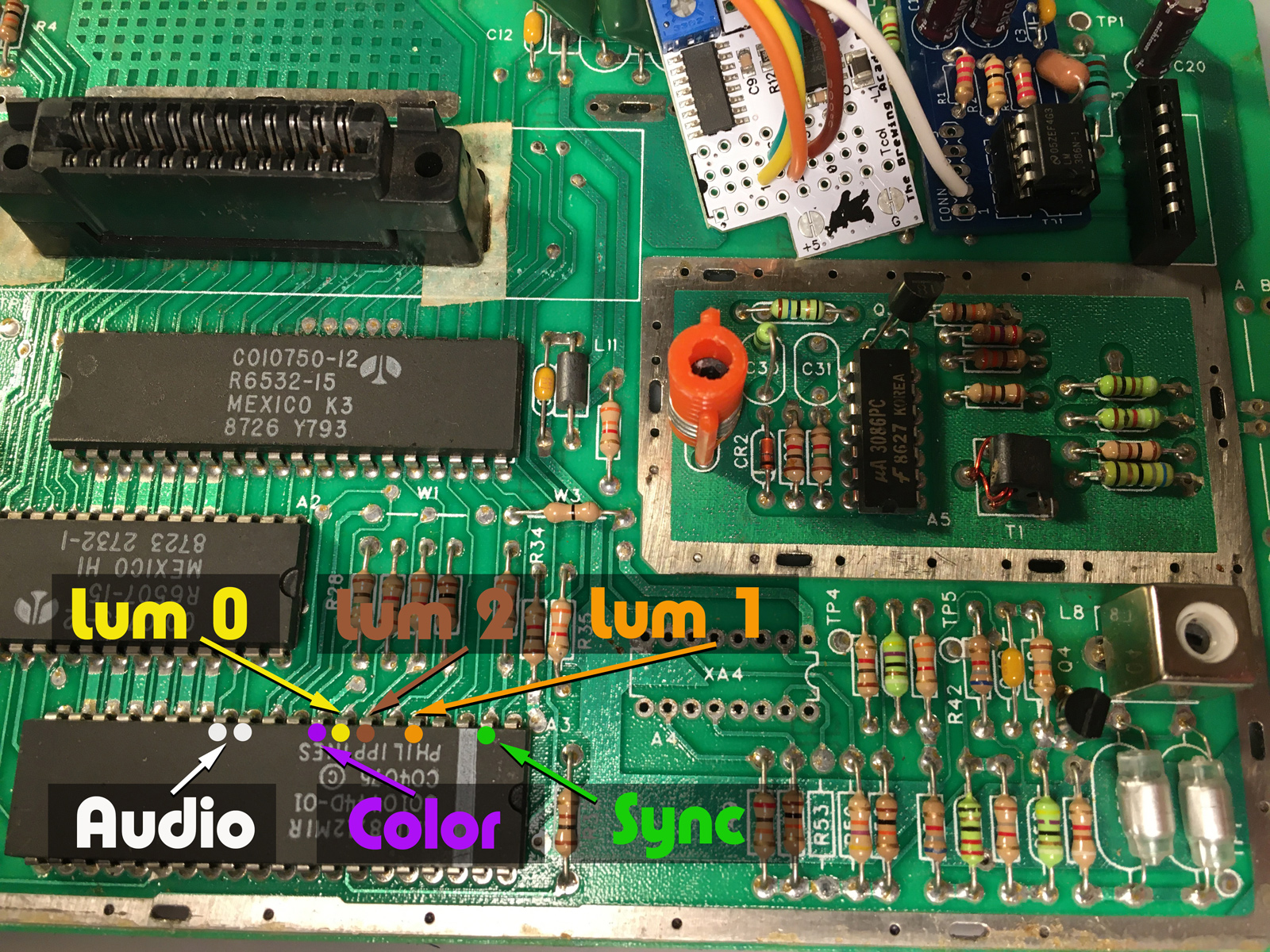
Now, I could just solder wires straight onto those pins. But that's harder than it needs to be, and again - reversibility. Let's find some easier places to attach wires.
The reason the UAV (presumably) uses the CD4050, is because some of the signals needed to generate video pass through it, and are therefore easily accessible.
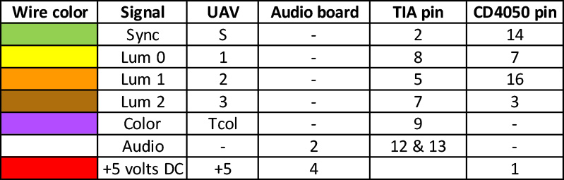
Let's update the chart again, this time to include the CD4050. While we're at it, let's add +5v as well, since we'll need that to power the UAV and audio boards:
What you won't find on the CD4050, are Color or Audio. So for the UAV mod, you will always need to go elsewhere to find those two signals. In this case, there are a couple of handy vias right near the TIA. Just below R28 for Color, and just to the upper right of the TIA (next to pin 1) for audio (this has both TIA audio channels combined).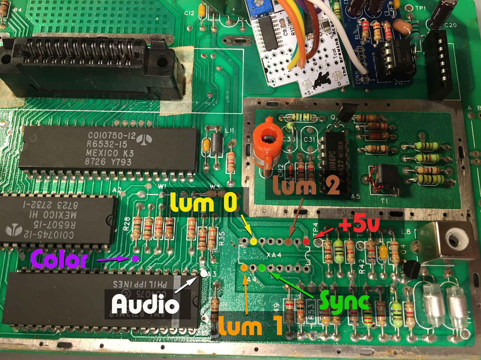
This shows us where the UAV was designed to get signals, but we're not using the CD4050 install method. And soldering to the CD4050's pins directly is not an option (in case you haven't been following along).
But a little sleuthing with a multimeter, and you can find alternative locations. You do have to end up soldering to the legs of three resistors (Sync, Lum 1 and Lum 2), but the rest are handy vias, which you can remove the solder from very easily with that desoldering iron you just bought for $24. ![]()
So with the connections sorted out (and wires routed, tested, measured and trimmed to length), It's Solderin' Time!™ I soldered the first wire in, then clipped the second to it to hold it in place, soldered that one...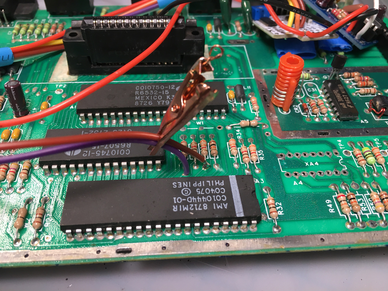
Then worked my way down the line...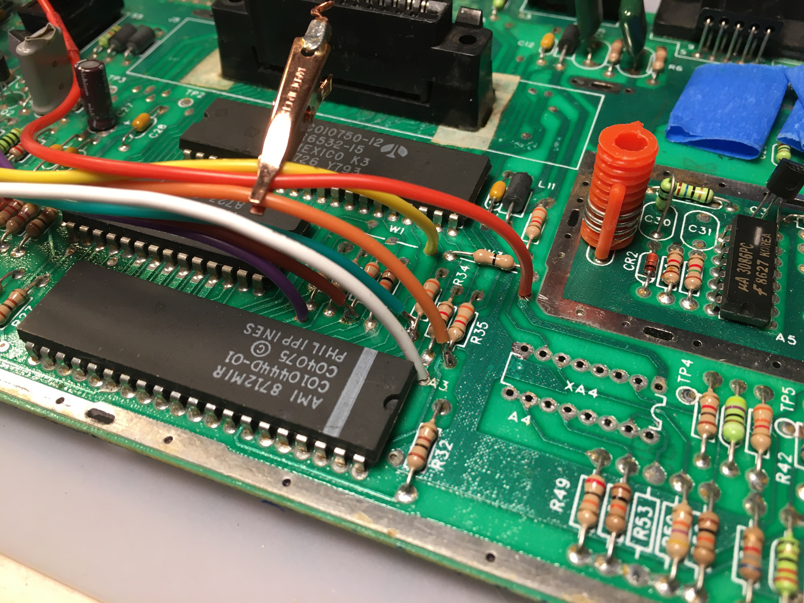
And yes - there's some folded-over masking tape up there to temporarily hold the mods in place while I work. Temporary. We'll get back to that.
Eventually, I got everything routed where I wanted it to go:
Don't forget to slide any heat shrink tubing onto the wires before you start soldering. ![]()
And yes, I put the CD4050 back. Socketed, this time: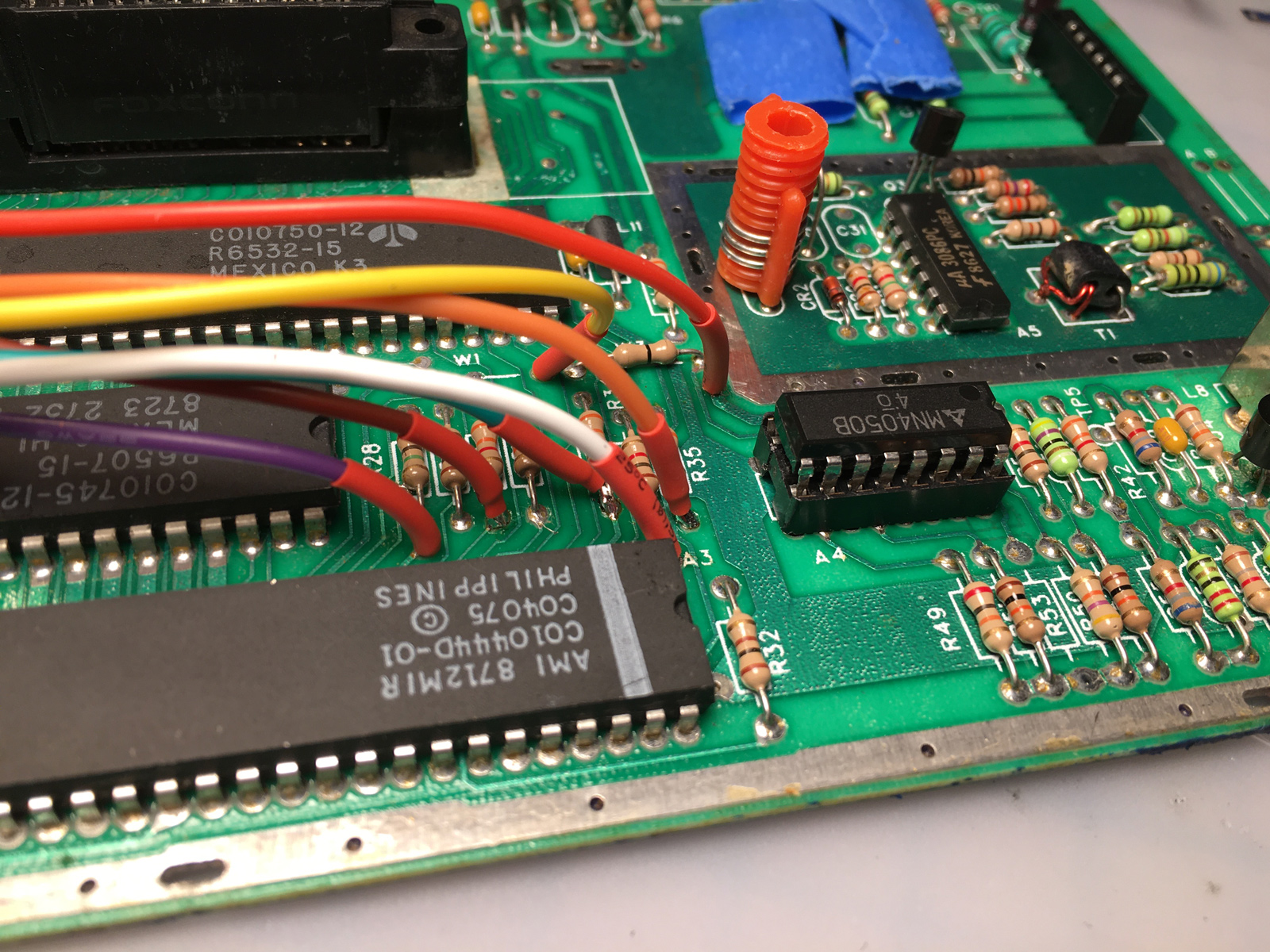
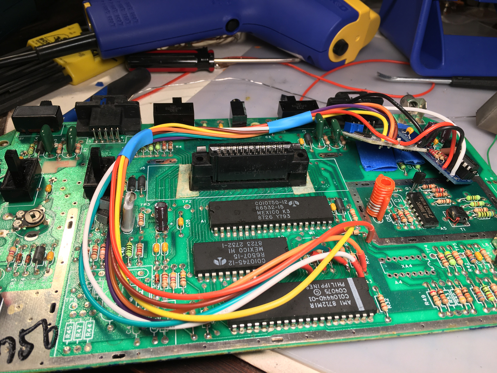
Then I temporarily installed the RF shield, to make sure everything still fit: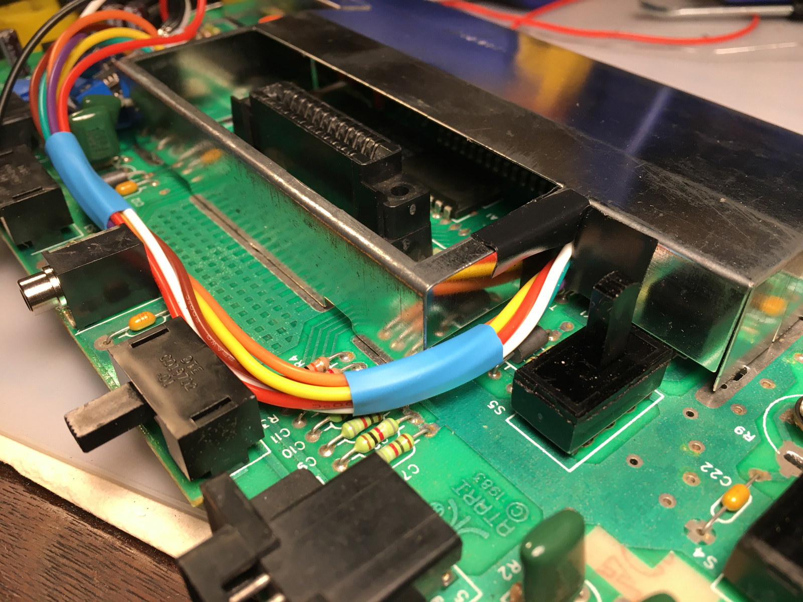
And I'm done! ![]()
No I'm not. ![]()
But the UAV is now connected to the Jr.
However, until I solder on the rest of the wires, I can't actually test this. But I've been checking continuity carefully as I've been going, so it all should work.
Right? ![]()
Published 2/24/23 5:20PM
-
 3
3

2 Comments
Recommended Comments