
Blogs
Our community blogs
-

- 5
entries - 9
comments - 7222
views
Recent Entries
 Latest Entry
TI 99/4A Memory Map
TI-99/4A Memory Map
>0000 Console Rom;
Interrupt vectors, XOP vectors
GPL Interpreter, Floating
POINT routines, XMLINK vectors,
>1FFF Low-level cassette DSR etc.
>2000 Low Memory Expansion Ram;
Varies according to the loader
used (Assembly). Generally
>3FFF not used by XBASIC programs.
>4000 DSR ROM;
Device service routines.
Determined by CRU bit setting
>5FFF Disk Controller, RS232 etc.
>6000 Cartridge Port (ROM & MINI MEM)
12k of XBASIC ROM. Upper 4k
@ >7000 - >7FFF is flipped to page in another 4k for a
>7FFF total of 12k.
>8000 RAM Memory Mapped Devices - VDP,GROM, SOUND, SPEECH.
>8000 Duplication of scratch pad RAM at >8300 - >83FF
>8100 Dup. as above
>8200 again
>8300 Scratch Pad RAM
>8400 Sound Chip
>8800 VDP READ DATA
>8802 VDP STATUS
>8BFF
>8C00 VDP WRITE DATA
>8C02 VDP READ/WRITE ADDRESS
>8FFF
>9000 SPEECH READ
>93FF
>9400 SPEECH WRITE
>97FF
>9800 GRON/GRAM READ DATA
>9802 GROM/GRAM READ ADDRESS
>9BFF
>9C00 GROM/GRAM WRITE DATA
>9C02 GROM/GRAM WRITE ADDRESS
>9FFF
>A000 HIGH MEMORY EXP RAM XBASIC high memory usage, Free space end pointed to by CPU RAM PAD address >8366
Numeric Values
Line Number Table
XBASIC Program Space >FFFF for a total of 24k bytes.
Additional Memory Space not in the CPU address space;
VDP RAM >0000 - >3FFF 16k bytes.
This is the console RAM space, and is separate from the rest of the CPU memory. Without memory expansion, XBASIC and BASIC programs reside here (BASIC does not use expansion memory.) (Assembly language does not use this area.)
BASIC does not use memory expansion at all. Only XBASIC, Assembly, FORTH etc. use it.
Chunks of memory are used by various peripherals as buffers, thus the amount indicated by CALL SIZE is right.
By using CALL FILES(1) followed by NEW, you can get back some, but disables the disk system. If you don't have it installed, but have mem exp. you will have more memory to use automatically.
Original Source as posted on July 8th 1984 by Gene Sampieri
The following is priceless as found in the below address:
http://www.unige.ch/medecine/nouspikel/ti99/tms9918a.htm#Registers
VDP memory
The videoprocessor has 16K of private RAM that it used to store the screen image, the character patterns and colors, and the sprite characteristics. Unless it is used in bit-map mode, only a small portion of this memory is effectively needed. The remaining is therefore available for use by the CPU. However all reading and writing operations must be carried on by the videoprocessor. The CPU passes the required address to the VDP as two bytes at address >8C02, and can then read bytes from >8800 or write bytes at >8C00. The VDP increments an internal pointer after each read/write operation. Contrarily to the GROMs, one cannot retrieve the value of this pointer from the VDP. Instead, address >8802 is used to read the VDP status register. This is definitely a slow way to access RAM, but it probably allowed to market the TI-99/4A at a much lower price, since RAM was fairly expensive in the 80s.
VDP registers
The first eight registers are used by the CPU to control the VDP. Very unfortunately, these are write-only registers, which means there is no way to determine the current display mode, unless it has been saved somewhere in RAM by the program that set it. Registers 0 and 1 contains control bits, registers 2 to 6 contains pointers to various tables in the VDP RAM and register 7 encodes 2 colors.
The VDP also contains a read-only status register that is uses to pass various information to the CPU.
VDP register 0
This register contains two control bits. All other bits must be zero. The register contains >00 after a reset.
Bit 6 (weight >02) selects a bitmap graphics mode when set to 1. VDP register 1 determines which bitmap mode is used.
Bit 7 (weight >01) enables external video input when set to 1.
VDP register 1
This register contains 7 control bits. All are set as 0 after a reset.
Bit 0 (weight >80) selects the memory size. For 4K of memory the bit is 0, for 16K it is 1.
Bit 1 (weight >40) enables the screen. When this bit is 0 the screen is blank.
Bit 2 (weight >20) enables interrupts. When this bit is 1, the VDP issues interrupt signals on the INT* pin each time it resumes refreshing the screen (vertical retrace signal).
Bit 3 (weight >10) selects text mode when set as 1. Bit 7 of register 0 can be set for bitmap text mode.
Bit 4 (weight >08) selects multicolor mode when set as 1. Bit 7 of register 0 can be set for bitmap multicolor mode.
If both bits 3 and 4 are 0, the display is in standard mode (or in bitmap mode, depending on register 0). Bits 3 and 4 should never be set together.
Bit 5 (weight >04) is reserved and should be 0.
Bit 6 (weight >02) selects the sprite size. When 0, sprites are 8x8 pixels. When 1, sprites are 16x16 pixels.
Bit 7 (weight >01) selects sprite magnification. When this bit is 1, each sprite pixel is replaced by a 2x2 pixels box.
VDP register 2
Defines the location of the screen image table. Only the last 4 bits are used, thus possible values for this register are >00 throught> 0F. The value is multiplied by >400 to find the location of the screen image table in the VDP memory. This table contains 1 byte for each character position on the screen (left to right, downwards), this byte contains the character number.
VDP register 3
Defines the location of the color table. Possible values are >00 through >FF and are multiplied by >40 to find the location of the color table. The table is not used in text mode, nor in multicolor mode.
In bitmap mode (i.e. when bit 6 in register 0 is set) the meaning of this register changes: bit 0 (weight >80) is the only one used to determine the address of the color table, which means the table has only two possible locations: >0000 or >2000. The remaining bits are used to define the table size, by the way of an address mask. This is done as follows: the righmost 7 bits are shifted left by 6 positions, filling the rightmost bits with 1s. The result will be a number between> 003F and >1FFF, which is ANDed with the address of a character in the table. As a result, the table can have any size between >40 and> 2000 bytes (however, note that the maximal usable size is >1800: 3 times >800 bytes).
VDP register 4
Defines the location of the character pattern table. Only the last 3 bits are used, thus possible values are >00 through >07. The value is multiplied by >800 to find the location of the character pattern table. Each entry in the table is eight bytes long and define the pattern of a character, in numeric order. Each byte in an entry defines one line of pixels in the character pattern: bits set as 1 result in foreground color pixels, bits set as 0 encode background color pixels.
In text mode (i.e. when bit 3 in register 1 is set) the last two bits of each byte are ignored since characters are only 6-pixel wide.
In bitmap mode (i.e. when bit 6 in register 0 is set) the structure of this register changes: bit 5 (weight >04) is the only one used to determine the address of the color table, which means the table has only two possible locations: >0000 or >2000. The two rightmost bits are used to determine the length of the table, by the way of an address mask. This is done by shifting them 11 positions to the left, filling the righmost bits with 1s. The result will be a number between >07FF and >1FFF that will be used as an address mask. At least, this is what happens in bitmap + text mode (i.e. when bit 3 of register 1 is set). In standard bitmap mode, the righmost bits are not necessarily 1: they are taken from VDP register 3, i.e. the address mask of the color table is used for both the color table and the pattern table addressing.
VDP register 5
Defines the location of the sprite attributes table. Only the last 7 bits are used, thus possible values are >00 through >7F. The value is multiplied by >80 to find the location of the sprite attributes table. Each entry in the table is four bytes long and defines a sprite position and color, in numerical order of sprites. See the chapter on sprites for a detailed description of this table.
VDP register 6
Defines the location of the sprite pattern table. Only the last 3 bits are used, thus possible values are >00 through >07. The value is multiplied by >800 to find the location of the sprite pattern table. Each entry in the table is eight bytes long and defines the pattern of a sprite, one byte per line. Bits that are set as 1 result on a pixel of the color defined for that sprite in the sprite attributes table, bits that are 0 result in a transparent pixel. If the large sprite size is selected (bit 6 in register 1 is set as 1) each entry is 32 bytes long and define a sprite as a set of 4 characters arranged as:
1 3
2 4
VDP register 7
The first nibble of this register defines the color of all characters in text mode. It is not used in the other modes.
The second nibble defines the background color wich is used for all characters in text mode. In all four modes it defines the color of the backdrop plane: this is the color of the screen outside the display area and the color that appears under transparents characters. When this color is set as transparent the external video image appears if it is enabled, black color appears otherwise.
Status register
The first 3 bits of this register are automatically reset as 0 when the register is read or when the VDP is reset. It ensues that the status register should only be read when an interrupt is pending, otherwise an interrupt could be missed.
Bit 0 (weight >80). This bit is set to 1 at the end of the raster scan of the last line of the display area (i.e. before drawing the bottom margin). If interrupts are enabled (by bit 2 in VDP register 1), the INT* pin is low when this bit is 1 and high when it's 0. This is why the status register should be read after each frame, in order to clear the interrupt and be ready to receive the interrupt at the end of the next frame. Also, if bit 2 in VR1 is cleared and set again while status bit 0 is set, an interrupt is issued immediately.
Bit 1 (weight >40) signals that there are 5 or more sprites on a given pixel row. Only the topmost four will be displayed.
Bit 1 (weight >20) is the coincidence bit. It is set when two sprites or more have at least one overlapping "on" pixel. This occurs even if the sprite color is transparent. Note that coincidence is checked only every 1/60th of second (1/50th of a second for the TMS9929A), thus if you change sprite positions during that time a coincidence could be missed.
Bits 3 to 7 contain the number of the 5th sprite on a pixel line, if any. This number is only meaningfull if bit 2 is set as 1 (else it may contain the number of the last displayed sprite, but no guaranty). If such a situation occurs more than once, the 5th sprite listed is the one closest to the top of the screen.
Summary of the VDP registers contents
Bit:
Weight: 0
> 80 1
> 40 2
> 20 3
> 10 4
> 08 5
> 04 6
> 02 7
> 01 VR0 0 0 0 0 0 0 Bitmap Ext vid VR1 16K Blank Int on Multic Text 0 Size 4 Mag 2x VR2 0 0 0 0 Screen image VR3
bitmap Color table Addr Address mask VR4
bitmap 0 0 0 0 0 Char pattern table 0 0 0 0 0 Addr Address mask VR5 0 Sprite attributs table VR6 0 0 0 0 0 Sprites pattern table VR7 Text color (in text mode) Backdrop color Status Int 5+ sp Coinc 5th sprite number
Video modes Standard mode (Graphic I)
This mode is selected by setting all mode bits as 0: bit 7 in register 0 and bits 3 and 4 in register 1. VR0: 0 VR1: 0 0
In this mode, the screen is divided into 24 rows of 32 characters. Each character is 8x8 pixels and has two colors: one for the "on" pixels (foreground color), one for the "off" pixels (background color). If a color is set as 0, the color of the backplane will be used (defined by register 7).
The screen image table is thus >300 bytes long (24x32=768). Each byte in the table contains the number of the character to display at the corresponding position on screen. This number is used to locate the character pattern in the pattern table and to look up its colors in the color table.
The color table is 32 bytes long. Each byte encodes the two colors for a group of 8 consecutive characters in numeric order (i.e. the first byte affects characters 0-7, the second characters 8-15, etc). In each byte, the first nibble encodes the foreground color, the second nibble the background color.
The character pattern table contains 256 entries, one per character in numeric order. Each entry is eight bytes long, each byte defines the pattern of one pixel row in the character: "1" bits set the pixel to the foreground color used for this character group, "0" bits set the pixel to the background color of this character group.--------| | 00000000 = >00| *** | 00111000 = >38| * * | 01000100 = >42| * * | 01000100 = >42| *** | 00111000 = >38| * | 00010000 = >10| *** | 00111000 = >38| * | 00010000 = >10 --------
The pattern table entry for the above character would be: >00 38 42 42 38 10 38 10
Sprites can be used in standard mode, see below.
Text mode
This mode is selected by setting bit 3 of VDP register 1 as 1. Bit 4 must be 0, as well as bit 7 of register 0. VR0: 0 VR1: 1 0
In this mode, the screen is devided into 24 rows of 40 characters. Each character is made of 8 rows of 6 pixels. All characters have the same two colors, defined by VDP register 7.
The screen image table is >3C0 bytes long (24x40=960).Each byte in the table contains the number of the character to display at the corresponding position on screen. This number is used to fetch the character pattern from the pattern table.
The color table is not used. The foreground color for each character is taken from the first nibble of VDP register 7, the background color is transparent, which lets the backdrop plane color appears. As the backdrop color is encoded by the second nibble of VDP register 7, one can consider that this register specifies both the foreground and background colors for each character.
The pattern table is organized just as in standard mode, except that the last two bits of each byte are ignored since characters are only 6-pixels wide in text mode.------| | 000000xx = >00| *** | 001110xx = >38| * *| 010001xx = >42| * *| 010001xx = >42| *** | 001110xx = >38| * | 000100xx = >10| *** | 001110xx = >38| * | 000100xx = >10 ------
Sprites are not available in text mode.
All this makes text mode the least memory-hungry mode: only a maximum of 3008 bytes (>0BC0) of VDP RAM is required in this mode. This can be further reduced by not using all 256 characters and/or by partly overlapping the tables.
Multicolor mode
This mode is selected by setting bit 4 of VDP register 1 as 1. Bit 3 must be 0, as well as bit 7 of register 0. VR0: 0 VR1: 0 1
In this mode, the screen is divided into 48 rows of 64 boxes. Each box is 4x4 pixel and can be independently assigned a color. The screen image table is still >300 bytes long, but each byte now represent a "character" made of 4 boxes. The boxes are arranged as:
0 1
2 3
The color of the boxes are defined in the character pattern table (!). Each entry in the table is 8 bytes long but only 2 bytes are used to define the colors of the 4 boxes that make up a character: >01 >23. To avoid wasting 6 bytes in each entries, the characters on 4 consecutive rows use the same entry, with an offset of 2 bytes:
characters on row 0, 4, 8, 12, 16 and 20 use bytes 0 and 1,
characters on row 1, 5, 9, 13, 17 and 21 used bytes 2 and 3,
characters on row 2, 6, 10, 14, 18 and 22 used bytes 4 and 5,
characters on rows 3, 7, 11, 15, 19 and 23 use bytes 6 and 7.
This reduces the size of this table to 1536 bytes (24 rows x 32 columns x 8 bytes).
The color table is not used in multicolor mode.
Sprites can be used in this mode.
To summarize, the screen organisation is the following:Column: 0 1 ... 31
Row 0: a b q r ... c d s tRow 1: e f u v g h w xRow 2: i j y z k l ...Row 3: m n o p
The corresponding screen image table could be:Column: 0 1 ... 31
Row 0: >00 >01 ... >1F Row 1: >00 >01 >1F Row 2: >00 >01 >1F Row 3: >00 >01 >1F
Row 4: >20 >21 >3F
...
And the pattern table would look like this (letters a-z represent the color of a given box, i.e. a digit in the range >0-F):Byte: 0 1 2 3 4 5 6 7Row: 0 1 2 3___
Entry >00: >ab >cd >ef >gh >ij >kl >mn >op
Entry >01: >qr >st >uv >wx >yz ...
...
This mode is fairly complicated to use (and does not yield very interesting results). A way to simplify it is to fill the screen with fixed character numbers, as shown in the above example. Drawing is then achieved by changing the color values in the character pattern table. Arranging the character numbers as in the example makes easier to calculate which byte must be changed in the pattern table, but there are other solutions.
Bitmap mode (Graphics II)
I'm sure every TI user had this great idea one day or the other: "Hey, lets fill the screen with all available characters: 0, 1, 2, etc. Then I can draw pixel-by-pixel by just changing definitions in the character pattern table". If you have tried, you must have realised there is a big problem: with 256 characters, we can only cover 1/3 of the screen. Not to mention the fact that the color table defines 8 characters at a time, which makes color drawings almost impossible. Bitmap mode takes care of these problems (sort of).
This mode is selected by setting bit 7 of register 0 as 1. Bits 3 and 4 in register 1 should be 0. VR0: 1 VR1: 0 0
In this mode, the screen is still devided in 24 row of 32 character, just as in standard mode. However, we now have three character pattern tables, one after the other: the first table applies to characters displayed in the top third of the screen (i.e. the first >100 bytes in the screen image table), the second to characters displayed in the middle third (bytes> 100-1FF) and the third to characters displayed in the bottom third of the screen (bytes >200-2FF in the screen image table).
Now we can fully cover the screen with non-redundent characters, by just writing >00, >01, >02 ... >FF three times in the screen image table. As the three pattern tables are consecutive, it is easy to calculate which byte is to be accessed to modify a given pixel.
There are also three color tables, arranged in the same way as pattern tables. Each entry in a table is eight bytes long and defines the colors for one character. Each byte in an entry defines the colors of a row in the character: the first nibble sets the pixel color for bits that are set as 1 in the pattern (foreground), the second sets the pixel color for the 0 bits in the pattern (background). The major drawback of this system is that each line of pixels in the display is chopped into 8-pixels clusters for which there is only a choice of two colors. This forces us to pay a lot of attention when drawing complex images, as 3 colors in a given pixel line must be at least 8 pixels appart.
Sprites are available in bitmap mode and work just as in standard mode.
Not so surprisingly, bitmap mode is extremely memory-hungry: it requires> 3300 bytes, not counting sprite tables.
To summarize, here is an example showing the correspondance between screen, pattern table entry and color table entry:Screen Pattern table Color table B 1 B B B B B 1 0 1 0 0 0 0 0 1 1 (black) B (l.yellow)B B 7 B B B 7 B 0 0 1 0 0 0 1 0 7 (cyan) BB B B C B C B B 0 0 0 1 0 1 0 0 C (green) BB B B B E B B B 0 0 0 0 1 0 0 0 E (gray) BB B B B 8 B B B 0 0 0 0 1 0 0 0 8 (m.red) BB B B B 5 B B B 0 0 0 0 1 0 0 0 5 (l.blue) BB B B B 6 B B B 0 0 0 0 1 0 0 0 6 (d.red) B2 2 2 2 D 2 2 2 0 0 0 0 1 0 0 0 D (magenta)2 (m.green)
The VDP register setting could be the following:
VR0 >02 Bitmap mode on
VR1 >C0 16K, screen on
VR2 >08 Screen image at >1800 (we can't have it at >0000 since either the pattern or the color table must be there)
VR3 >FF Color table at >2000, address mask = >1FFF (full size table: 3 times >800 bytes)
VR4 >03 Pattern table at >0000, address mask = >1FFF (full size table: 3 times >800 bytes)
Hybrid bitmap modes
Note that the trick of covering the screen with three repeats of characters 0-255 is just an easy way to calculate which byte corresponds to which pixel, this is by no means an obligation. You could use the tables just the way you do in standard mode: having fixed pattern definitions (and colors) and placing a character number in the screen image table to display it. The address masking trick becomes very handy in this case. Rather than having three copies of the pattern table one after the other, let's just have one and set the address mask to 0: in the example above, VR4 would become >00. The advantage over standard mode is that we can set different colors for each character (rather than for a group of . In fact, we can even set a color pair for each pixel row in a character: this is a nice way to create iridescent characters!
Finally, both solutions can be mixed in the various thirds of the screen: the top two thirds could be arranged for easy bitmap drawing, whereas the bottom third could be arranged for rapid character writing. Some games use this solution to display prompts and scores at the bottom (or top) of the game screen.
You can use the mask bits in register 4 to assign a >800-byte pattern table to each third of the screen:
> 00 (or >04): only one pattern table, identical for each third of the screen.
> 01 (or >05): two pattern tables. One at >0000 (or >2000) for the 1rst and 3rd thirds, one at >0800 (or >2800) for the middle third of the screen.
> 02 (or >06): two pattern tables. One at >0000 (or >2000) for the 1rst and 2nd thirds, one at >1000 (or >3000) for the bottom third of the sceen.
> 03 (or >07): three pattern tables. One at >0000 (or >2000) for the 1rst third, one at >0800 (or >2800) for the 2nd third and one at >1000 (or >3000) for the bottom third of the screen.
Then we could do the same for the color table, using bits 1 and 2 (weight> 40 and >20) to select the number of tables. The remaining bits will affect character grouping within a table. Since they also affect grouping whitin the pattern table, we'd better be carefull with these!
In summary, these would be the addresses of the tables in 8 possible situations:
VR3 VR4 Mask Top 3rd Middle 3rd Bottom 3rd >1F >00 >07FF >0000 >0000 >0000 >9F >04 >07FF >2000 >2000 >2000 >3F >01 >0FFF >0000 >0800 >0000 >BF >05 >0FFF >2000 >2800 >2000 >5F >02 >17FF >0000 >0000 >1000 >DF >06 >17FF >2000 >2000 >3000 >7F >03 >1FFF >0000 >0800 >1000 >FF >07 >1FFF >2000 >2800 >3000
To group characters within a table, we could further alter the color table mask:- VR3 = >0F results in >400-byte tables. This means that characters> 80-FF will have the same colors and definitions than characters> 00-7F.
- VR3 = >07 results in >200-byte tables. This means that characters> 40-7F, >80-BF and >C0-FF will have the same colors and definitions than characters >00-3F.
- At the extreme, VR3 = >00 results in >40-byte tables. As there are 8 bytes per characters, this means characters are arranged in 8 groups of 32 identical characters: chars 0-7 are identical to chars 8-15, 16-23, etc.
- We could even get weird grouping schemes by using values like> 02,> 04, >55, etc.
The table below lists the six most logical values, plus two gooffy ones (just for fun).
VR3 Mask Character grouping Chars Repeats >00 >003F 0=8=16...=248
1=9=17...=249
7=15=23...=255 8 32 >01 >007F 0=16=32...=240
1=17=33...=241
15=31=47..=255 16 16 >03 >00FF 0=32=64...=216
1=33=65...=217
31=63=95...=255 32 8 >07 >01FF 0=64=128=192
1=65=129=193
63=127=191=255 64 4 >0F >03FF 0=128
1=129
127=255 128 2 >1F >07FF Each char is unique 256 1 >02 >00BF 0=8=32=40...
4=12=36=44... 16 16 >04 >013F 0=8=16=24=64...
32=40=48=56=96... 16 16
Bitmap text mode
This is the mode TI forgot to tell us about. It works just like standard bitmap mode, except that the screen is now 40 columns and that only two colors are available.
This mode is selected by setting bit 7 of register 0 as 1. Bit 4 in register 1 should be 1. VR0: 1 VR1: 0 1
The screen is now divided in three, each third is 8 lines high and thus occupies >140 bytes in the screen image table (8*40=320).
The colors are taken from VR7, just like in regular text mode. There is no color table, and the contents of VR3 is irrelevant.
Just like in standard bitmap mode, there can be upto 3 pattern tables, located either at >0000 or at >2000. You can use the address mask bits in VR4 to determine which third of the screen uses which table. The main difference is that the color address mask is not used to fill-in the patten address mask: >07FF is always used instead. No character grouping to worry about, then! This mode comes handy for black-and-white drawings.
Bitmap multicolor mode
Another undocumented mode. It works as a mixture of bitmap and multicolor mode.
This mode is selected by setting bit 7 of register 0 as 1. Bit 3 in register 1 should be 1. VR0: 1 VR1: 1 0
The screen is now divided in three, each third is 8 lines high and thus occupies >100 bytes in the screen image table (8*32=256).
Just like in standard multicolor mode, there is no color table and the contents of VR3 is irrelevant.
The color of the boxes are taken from upto 3 pattern tables, located either at >0000 or at >2000. You can use the address mask bits in VR4 to determine which third of the screen uses which table. Since a single table would be sufficient for this purpose, there is no real point in using this combined mode...
Illegal modes
It is not allowed to set text and multicolor mode together, whether in bitmap mode or not. VR0: x VR1: 1 1
If you try, the VDP will display a fixed image, that is not influenced by the contents of the VDP memory, nor by registers VR2 to VR6 (sprites are not available). The screen is 192 pixel lines and 40 columns. Each column is made of 4 pixels in foreground color, followed by 2 pixels in backgroud color. These two colors are taken from VR7.
Sprites
Sprites are special characters that can be displayed at any position on screen, i.e they are not limited to a grid or rows/column, instead each sprite position can be defined with a precision of one pixel.
Sprites can be either 8x8 pixels or 16x16 pixels depending on the setting of bit 6 in VDP register 1: when this bit is 0 all sprites are 8x8, when it is 1 all sprites are 16x16. In addition, bit 7 in VDP register 1 provides a mgnification feature: when this bit is 1 all sprites are magnified by a factor of two. Concretely this means that each "pixel" becomes a 2x2 pixels box.
Each sprite can have its own foreground color. The background color is always transparent, which lets the underlying image appear under the sprite.
Upto 32 sprites can be displayed at a time. Each one can be seen as an extra image plane on the top of the screen, overlapping each others, with sprite number 0 at the top. Thus the virtual image planes are:
- Black
- External video
- Backdrop plane (color in VDP reg 7)
- Image plane (characters)
- Sprite number 31
- Sprite number 30
- etc upto:
- Sprite number 0
There is one restriction however: the VDP cannot display more than 4 sprites on a given line of pixels. Thus, if 5 sprites or more must be drawn on the same line, only the topmost four (those with the smallest numbers) can be displayed. The number of the 5th one is placed in the status register together with a flag bit and the others are ignored. This occurs whether or not the sprites are actually overlapping: one could be on the left of the screen, the other on the right with the same result.
Coincidence is a different condition: whenever two "on" pixels in different sprites occupy the same screen location, a bit is set in the VDP status register. This comes handy for games programming: an easy way to check whether the bullet hits the target. Note however that the VDP does not tell you which are the overlapping sprites...
Sprites characteristics are defined in two tables pointed by VDP registers 5 and 6: the sprite attributes table and the sprite patterns table.
Sprite attributes table
This table is pointed at by VDP register 6. It contains upto 32 entries for the 32 sprites arranged in numeric order. Each entry is four bytes long, thus the maximum size for this table is >100 bytes. The four bytes define sprite characteristics as follows:
Byte 1 Byte 2 Byte 3 Byte 4 Sprite 0 vertical position -1 horizontal position pattern number clock bit sprite color Sprite 1
"
"
"
"
"
Sprite positions are expressed in pixels relative to the top left corner of the display area. This will be the position of the top leftmost pixel of the sprite (unless the early clock bit is set, see below). Note that the vertical position coordinate in the table is offset by one: therefore the topmost pixel line is >FF, the second is >00, the third is> 01 and the last is >BE. Any sprite whose vertical position is greater than> BE won't be visible on screen, although coordinates close to >FF can result in the bottom of the sprite appearing at the top of the screen. Similarly, row values just under >BE result in partly blending off the bottom of the sprite.
The same thing is true for sprite approaching the right border of the screen (horizontal coordinates close to >FF): the sprite appears to blend-in from the right. However this won't work on the left of the screen: when the horizontal position is 0 the whole sprite is visible, when it's lower than 0 (i.e. >FF, >FE, etc), the sprite appears at the right of the screen. To allow for sprite blend-in from the left of the screen one can set the "early clock" bit (bit 0, value >80) in the color byte: the horizontal coordinate now refers to a point located 32 pixels to the right of the upper left corner of the sprite. This results in shifting the sprite 32 pixels to the left and allows for partial disappearance on the left side (but not any more on the right).
The pattern number refers to the entry containing the sprite pattern in the sprite pattern table.
Finally the sprite color is defined by the right nibble in the byte 4 of the entry.
The sprite attributes table does not need to define all sprites: if the vertical position of a sprite is set as >D0, the sprite won't be displayed (as it's off-screen), but neither will any of the following sprites. This comes handy to quickly erase all sprites by just changing one byte in the attributes table.
Sprite pattern table
This table contains patterns to be used by the various sprites, arranged in ascending order. Each entry is either 8 bytes long or 32 bytes long depending on the sprite size.
If the sprite size is set as 8x8, entries are 8 bytes long. Each byte defines a row in the sprite: "1" bits result in pixels of the color specified for that sprite in the attributes table, "0" bits encode transparent pixels and are ignored for display purposes.
If the sprite size is set as 16x16 (VDP register 1, bit 6 set as 1) each entry is 32 bytes long. These bytes define the sprite pattern as if it were made of four "normal sprites" arranged in a 2x2 formation:
1 3
2 4
Thus, bytes 0-7 define the top left quadrant, one byte per line of 8 pixels. Bytes 8-15 define the bottom left quadrant in a similar fashion. Bytes 16-23 define the top right quadrant, one byte per line of 8 pixels (which now corresponds to pixels 9-15 of the sprite rows 0-7) and bytes 17-23 define the lower right quadrant.
Even wiith a 16x16 pixels size, 32 sprites require at most >400 bytes (32x32). Thus there is room enough for extra sprite patterns and a sprite can be animated by quickly changing its pattern number in the attributes table rather than by modifying the sprite pattern table.
Timing issues
The VDP needs 2 microseconds to read or write a byte to its RAM. In addition, it can only communicate with the CPU at precise moments, when it is not too busy with building the screen. Such moments are known as CPU access windows and may arise at various intervals depending on the video mode. In standard or bitmap mode, a window occurs every 16 memory cycles, each cycle being 372 ns long. This means the VDP may have to wait upto 5.95 us before a CPU access window occurs. Adding the 2 us needed for RAM access gives us a maximum delay time of 8 us. Of course, it can be as fast as 2 us if a window just happens to open (even less for reading operations, thanks to the read-ahead buffer). In text mode, a window opens every three memory cycles, i.e. at intervals of 1.1 us. In multicolor mode, a window opens every four memory cycles, i.e. at 1.5 us intervals.
There are two exceptions to these rules, however:- When the screen is blank (because bit 1 in register 1 is set as 0) the VDP does not handle the screen and a CPU access window is permanently open. Consequently, there is no wait time.
- When the VDP is done with drawing a frame and enters vertical refresh mode it issues an interrupt (if enabled) and opens a 4.3 milliseconds (4300 us) window for CPU access.
Condition Mode RAM access
delay Time waiting
for a window Total delay Building screen Standard
/ Bitmap 2 us 0 - 5.95 us 2 - 8 us Building screen Text 2 us 0 - 1.1 us 2 - 3.1 us Building screen Multicolor 2 us 0 - 1.5 us 2 - 3.5 us Vertical retrace Any 2 us 0 2 us Blank screen Any 2 us 0 2 us
Contrarily to standard memory, the VDP cannot hold the CPU in a wait state until it is ready to accept/send data. This means that the application program must contain appropriate delays to prevent the CPU from going on with the next operation before the VDP has completed the current one. A typical example is passing the two command bytes to the VDP: using two successive MOV instructions is too fast and the second byte won't be read. The program should thus contain another instruction in between the two MOV (such as a NOP or a SWPB).
Programming examples
*------------------------------------------------------------* VDP write to register. * Expects register # in R0 MSB and register content in R0 LSB*------------------------------------------------------------VWREG ORI R0,>8000 Set command bits as 1xxx xrrrCMD SWPB R0 Send a command to the VDP MOVB R0,@>8C02 Send first byte (least significant) SWPB R0 Delay MOVB R0,@>8C02 Send second byte (most significant) B *R11*------------------------------------------------------------* VDP set address to write in RAM* Expects address in R0*------------------------------------------------------------VAD2WR ANDI R0,>7FFF Make sure command bits are 01xx xxxx ORI R0,>4000 JMP CMD Send command*------------------------------------------------------------* VDP set address to read from RAM* Expects address in R0*------------------------------------------------------------VAD2RD ANDI R0,>3FFF Make sure command bits are 00xx xxxx JMP CMD Send command*------------------------------------------------------------* VDP write byte to RAM* Expects data byte in R0 MSB and address set by VAD2WR*------------------------------------------------------------VWRBYT MOV R0,@>8C00 Send data to VDP B *R11 Delay*------------------------------------------------------------* VDP read byte from RAM. Assumes address was set by VAD2RD* Result will be in R0 MSB*------------------------------------------------------------VRDBYT MOV @>8800,R0 Get data byte B *R11 Delay*------------------------------------------------------------* VDP read status. Result will be in R0 MSB*------------------------------------------------------------VRDSTA MOV @>8802,R0 Read status register, resets bits 0-2. B *R11 Delay
- Read more...
- 0 comments
- 5
-
 Latest Entry
Firmware Vx.40
Hello all,
after almost 3 years a new Firmware is ready for download.
And yes, you remember correct, i started the entry 3 years ago with similar wording.
What is new?
- the content is shown in the menu
- auto-size mode for *.lnx-files
- modify up to 128Bytes at once for 93Cx6 chip
- code optimation (e.g. Flash erase routine)
- Support of 93C66 and 93C86* for all functions with USB (93C66 and 93C86* was requested from some developers - *93C86 only for Board 6)
- only Board 1 with PCB 1.3d4:
- bank mode available - 2 independet banks with 512KB (possible to switch back to fast-erase mode as before)
- It is possible to switch between the banks if the FlashCard is inserted into the Lynx. As long as the LED is flashing, it is possible to press Anykey to change to the other bank.
- To use the changed bank, the Lynx must be switched off and on again.
- only Board 1 with PCB 1.3a4 limited edition:
- optimation of demo cancle - the FlashCard do no longer start up the demo again if the demo is cancled to early (only 25th anni!)
- If the FlashCard is inserted into the Lynx, it is possible to activate and deactivate the demo as long as the status LED is flashing by using the Ankey
- To use the changed demo setting, the Lynx must be switched off and on again.
- Easteregg
Please use "Firmware V140N 20160107 Language V140x.fcb1" for Board 1 FlashCard.
(PCB V1.271/1.276/1.280/1.3a4/1.3d4)
Please use "Firmware V640N 20160107 Language V640s.fcb6" for Board 6 FlashCard.
(PCB V1.913/1.923)
Please note: at first use after Firmware update the FlashCard will ask to press the Anykey to initialize some parameters.
The FlashCard only accept a Firmware file which work with the FlashCard! If the FlashCard do not accept you tried the wrong Firmware file!
For details about the update please read the manual!
The manual is available in English (en) and German (dt).
Kind Regards
LynxmanFlashCard Manual 1_40_en.pdf FlashCard Manual 6_40_en.pdf FlashCard Manual 1_40_dt.pdf FlashCard Manual 6_40_dt.pdf Firmware V140N 20160107 Language V140x.zip Firmware V640N 20160107 Language V640s.zip
-
After 5 years of collecting I finally got one of the games I wanted from the beginning, Halloween on Atari 2600. The version I decided to finally purchase was the game with no label. Just a white sticker with the word "Halloween" written in orange across it. The story behind this version was that Wizard Video was liquidating their inventory so in order to save money they stopped producing labels and just wrote the names of the game on the cartridge. This raises an interesting question which i've never really seen an answer for. Which version is more rare? Of course the rarity guide has the no label version at an 8 and the label version at a 7, but in the description of the non label version it reads, "It is not clear which one is more rare"... Well in my 5 years of looking for this game waiting to finally get one for my collection I have seen a lot more labeled versions than non labeled versions for sale on the internet. Now this doesn't exactly mean that the non label version is more rare, but it stands for something. In the 5 years of collecting I have seen the label version for sale in a retail store but have NEVER seen the no label version for sale. It is a very compelling argument that I do not have a confident answer for. If I were to give my best guess from what i've seen over the years the no label version is more rare and hard to find. Either way it is unclear how many of these carts are out there and it remains one of the hardest to find games in the atari 2600 library.
- Read more...
- 0 comments
-
- 3
entries - 2
comments - 4808
views
Recent Entries
Latest Entry
Scott Adams

Scott Adams is a familiar name in the TI community, outside of this community one could mix him up with the other Scott Adams who writes comic strips about Dilbert and although they are both story tellers in some way our Scott is not just a story teller but an expert coder and creator of the adventure style games.
Scott Adams, the genius behind many Text adventure games was brought up in Miami Florida. In 1975 he wrote a computer game on a computer that his brother Richard built a year before, making him the first person on earth to write a computer game on a home computer. The full story of how Richard came to build this machine, well before Steve Wozniac built Apple 1 can be read in great detail in the link below:
http://exoticsciences.com/sa.htm
The following is a writeup given to me directly from Scott Adams himself. At first I intended to polish it up but then I realised that this in itself is a part of history that should remain as intact as possible.
"I grew up in North Miami Beach and always had a love for science, I remember as a child in the early 60s going on a tour of the University of Miami and seeing the computer science department and waiting to go inside. I was active in local science fairs and won some awards as well as being written up in articles in the newspaper. IN high school as an experiment the state of Florida allowed one remote terminal in our high school math lab to the U of M mainframe and it was running APL/360. My first major program was tic tac toe that would always win. I would go into school before it opened and had permission to be let in by the janitors and after school I would stay until late, locking up the school behind me.
My brother build from chip slice cpus a homebrew computer which I then programmed in machine language a game for (more info on my webpage on a sidebar on this). I also had the first ever Sphere computer homekit which I then proceeded to mod with a my own designed graphics card and wrote a tank war game for. I won the first ever “what do you use your Sphere for” contest with the company.
I was working at Stromberg Carlson in lake Mary Fl as a software engineer when I purchased my first “appliance” computer, ie a computer I didn’t have to build to use J I wanted to learn the BASIC language on it and thought the concept of strings was interesting so I wanted to write a game that let you use English language somehow. At work the IT dept got a copy of Crowther and Woods Adventure! And I was able to get a password to play it. I came in all week before work ad stayed at night to play until I beat it. I decided I want to write a similar game for my TRS-80 model I. Other engineers there laughed at me and said this was running on the mainframe and my toy computer could never handle it. I ended up invented my own language which I emulated in BASIC and wrote my first Adventure game.
Before Stromberg, I got my degree in Computer Science for Florida Institute of Technology (now known as Florida Tech). I worked downrange on the Air Force Eastern Test Range as a Space Object Identifier Analyst at radar stations. But there was a mainframe there and I loved to program so I got permission to make some major mods to the software they were using even though I wasn’t hired as a programmer. I got a number of commendations for some things I did. At one radar station on Antigua Island they only ran it for the day shift, so I was able to use the machine in the evenings for myself. I got a copy of a Fortran Star Trek game that played on the teletype. I then proceed to covert it to run on the radar screens instead and in effect turned the multi-millionaire dollar radar tracking station into a giant video game J great fun.
Return to Pirates Island was written in my own proprietary database adventure language like all my adventure games. I wrote them on one machine then transferred the databases to other machines to execute. RTPI was special in it was originally only for the TI and also was the world’s first adventure game to have graphics in a game cartridge. I also developed a special program to be able to get the graphics to fit. Instead of graphical compression as used today I came up with making the pictures of pieces of other pictures and then having an artist make this picture based on these smaller pieces. It ran very fast but was very labor intensive for the poor artist as you might imagine."
I thank Scott for sending me this small Bio. He is a very humble and inspiring person, one who gave us many hours of entertainment and made our world a little better.


- Read more...
- 0 comments
- 3
-
- 17
entries - 6
comments - 7274
views
Recent Entries
 Latest Entry
11/30/15 - Photograph
I've been busy and could not think of who sang this song. It finally hit me yesterday so I'm putting it up. For the past 10 days, my sleeping habits have been horrible and I can't say any one song has been there when I woke up. So there are no entries from 12/1 to 12/10. This was the one on 11/30, so I"m posting it. I knew the song, couldn't find it when typing the title, until I remembered the band. It is Photograph by Def Leppard.
Phil
- Read more...
- 0 comments
- 17
-
 Latest Entry
This is my blog introduction. read it
um hello. This is my blog. I like to play games and stuff. Call of Duty is one of my favorite series ATM. Xbox 360 is my main console but I also play on mobile, Game Boy Advance SP, super nintendo, PS2, Wii, and Atari 2600 as well as Plug N Plays every once in a while. I also love Star Wars. This is all I have time to write. I will hopefully do more entries later. Bye readers!

- Read more...
- 0 comments
-
- 4
entries - 0
comments - 14842
views
Recent Entries
Some days ago, while listening to some of the Zelda II soundtrack, I noticed something - it's possible you may have noticed it too. Zelda II's soundtrack sounds inherently different from the original Zelda. And not just due to the composer, either - (Koji Kondo in The Legend of Zelda, while Akito Nakatsuka did the music for Zelda II: The Adventure of Link in his only Zelda compositional work. Interested readers may like to know that his Dungeon Theme from the game was used as the StreetPass Battle Theme in The Legend of Zelda: A Link Between Worlds. Rather the remix [as it is now orchestral] was done by Nakatsuka himself or the game's composer Ryo Nagamatsu is unknown, but I am of the opinion that it is the work of Nagamatsu as Nakatsuka does very little compositional work these days.) -it sounds like it's using different 8-bit 'instruments' from the original Zelda.
A portion of this may be down to the technique of the composers. I however and of the opinion that this down to the sound programming - in particular, the sound driver used. You see, in these early days of gaming, there was no standardized software. Composers were often also proficient programmers, so each composer might program his own sound driver. Of course, you'd get the rare occasion where a programmer would have to do the music as they couldn't afford a composer, but we do not speak of these.
I did some digging at this website for information, having stumbled upon it months ago and remembering a mention of sound drivers. And with that - success! Nintendo used three sound drivers on the NES. The first was programmed by Hirokazu Tanaka (at the time he started working at Nintendo, there was no sound driver for the Famicom, so he programmed one himself), the second by Akito Nakatsuka (initially he used Tanaka's before programming his own around 1986.) and the third by Koji Kondo (Nintendo required its main composers to write their own sound drivers, so Kondo did likewise). It is safe to assume that Kondo used his own sound driver for his Zelda music, thus, given the different sound of the Zelda II soundtrack, one can only guess that Nakatsuka likewise used his sound driver for Zelda II's music.
A mystery solved. But one does wonder: what games had what sound driver? Kondo's (and possibly Tanaka's and probably many, many other company's sound drivers) fit the definition of 'classical' 8-bit music. Nakatsuka's doesn't. Metaphorically, it's the sitar to Kondo's pizzicato violin. Going off of only the Zelda game's, Nakatsuka's is immediately different from the first Zelda, and thus, Kondo's driver. One further distinction is that his driver seems peculiarly weak at the higher pitches, as the Zelda II title theme shows off.
Something to wonder. Perhaps one day we may know, either through guesswork or someone managing to get their hands on information straight from the Yoshi's mouth.
- Read more...
- 0 comments
- 4
-
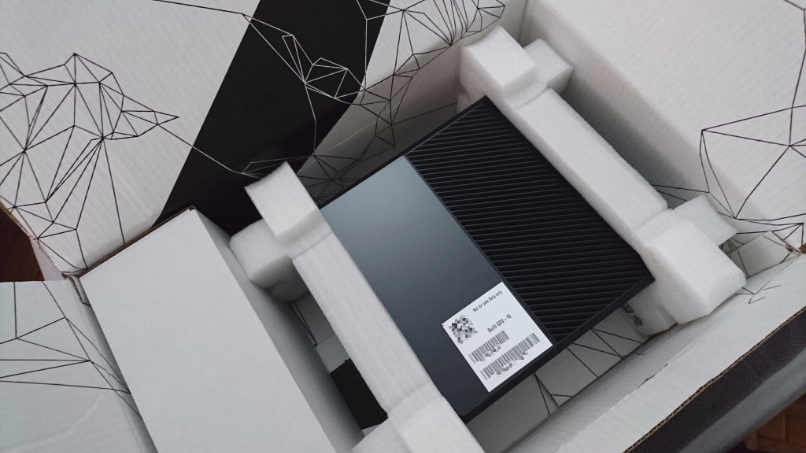
Microsoft Xbox One XDK Development Kit (Prototype/Beta) and TestKit (Beta)
Purchased directly from the PRESIDENT of a closed videogame company, complete in box and in like new condition, for sale really hard to find Xbox One Development Kit and Testing Kits!
Item are located in Europe, I offer express shipping with SDA courier, the cheaper and fast way to send from here, delivery in 4-6 days for Europe and 6-8 days for USA (shipping cost not included).
I can't offer standard PayPal payment for these transactions (only payment for friends/other is allowed) or can use any other payment like Payza (2.5% + € 3 fee) and Skrill to works like PP, or Bank transfer without any extra fee.
Microsoft Xbox One Beta Development Kit XDK – Prototype.
Available: 2 with Original Box!
Price: € 2349 (Only $ 2500)
Microsoft Xbox One Beta Testing Kit XDK – Test.
Available: 2 with Original Box!
Price: € 1399 (Only $ 1500)
Microsoft XBOX One XDK (Beta/Prototype) DEV/Development Kit with Original Development Box (Like New/Used). € 2349 ($ 2500 USD)
(No software or tools are included in the price! No PayPal, Available only 2 kits!) More Pictures: http://goo.gl/AM6HmY
Microsoft XBOX One XDK (Beta) TEST/Testing Kit with Original Development Box (Like New/Used). € 1399 ($ 1500 USD)
(No software are tools are included in the price! No PayPal, Available only 2 kits) More Pictures: http://goo.gl/WMTG6m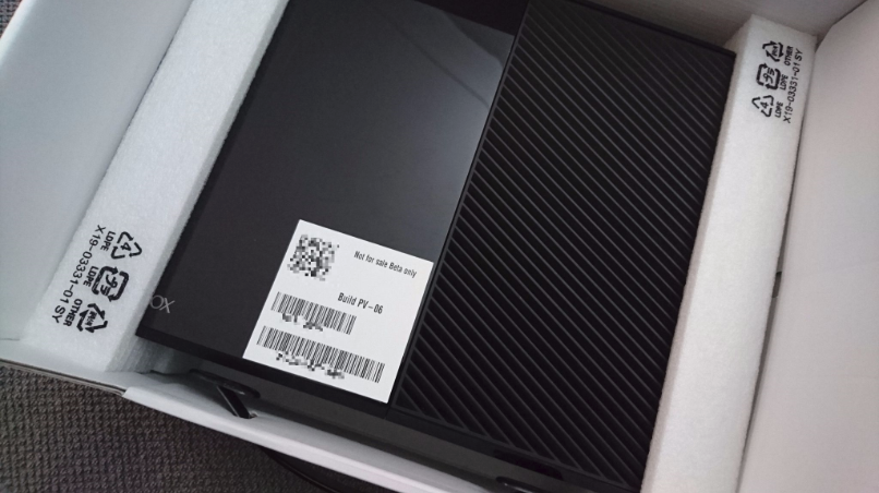
NOTE: For feedback and more info please check my eBay profile (ID: 20yearsofplay)For details, questions, please send private message, but don't ask me about "technical" questions as no information will be given.
Note, these comes with QR codes, serial numbers and more, nothing was removed, I just removed these details from the images! not sure you will ever have another possibility to purchase this kit.
We do not sign any NDA, we don’t have any contract and these kits are NOT more property of Microsoft as they allowed the re-sale and not return from the Devs.
Let’s talk about "Real" Developers prices, we have $ 1700 for Test Kit and $ 3750 for Development Kit, this price does not include any ID support, just hardware.
I don't have possibility to order more than these 4 kits, so this is the first and last time to you will see these for sale.
Feel free to send me private message, or contact me directly at: XDK.development@gmail.comYou can add me on Google+ as “Xbox One Development” or follow me here on eBay.
Note before purchase
No development software/tools are included, but you can find these online for free download.
Items are located in Europe, of course I don’t keep these at home, but are ready to be send.
Available also huge quantity of PlayStation 4 Development and Testing Kits for pre-order and some located in Europe ready to be send.
You can also check my personal online store at this page: https://goo.gl/6CSR73 (copy and paste in your browser) to access the gallery and price list.
Note about rumours (False)
There are plenty of rumours going around about how easy and cheap it is to build for consoles… and with declining mobile app sales, this is what peaked my interest in the first place.
First, a quick response for the many inaccurate “news articles” around the internet regarding console development.
If you read “Any Xbox One can be a Development Kit” this is false!
And according to the ID team, in 2016 Microsoft will be push Windows10 to Xbox One after it finishes releasing it on mobile and desktop, during this process, developers with Windows10 and Windows10 Universal applications can make changes to allow for Xbox One support - and Microsoft is hoping that Xbox One can be locally developer unlocked at that time.
Right now they have a very limited amount of development systems, and have been only selecting larger companies with games ready to release at any minute.
Another rumours is “Xbox One is targeting Indie Developers” another false news.
This actually won’t be in effect until 2016, if ever! right now they are actively seeking games that are complete and “high volume” from publishers.
What about the “Xbox One DevKit cost $ 500”? yes, also this one is false, there are not Dev/Test Kit for XB1 to cost $ 500 USD, development kits prices are protected by NDA, so you will not read all these prices around every media website if will be true.
Thanks for reading and watching!
- Read more...
- 0 comments
-
 Latest Entry
Video games is good for your brain
The enhanced learning of the regularity and structure of environments may act as a core mechanism by which action video game play influences performance in perception, attention, and cognition.
Video games have an appeal that crosses many demographic boundaries, such as age, gender, ethnicity, or educational attainment. They can be used to help set goals and rehearse working toward them, provide feedback, reinforcement, self-esteem, and maintain a record of behavioral change.
Their interactivity can stimulate learning, allowing individuals to experience novelty, curiosity and challenge that stimulates learning. There is the opportunity to develop transferable skills, or practice challenging or extraordinary activities, such as flight simulators, or simulated operations.Whether playing video games has negative effects is something that has been debated for 30 years, in much the same way that rock and roll, television, and even the novel faced similar criticisms in their time.
Purported negative effects jocuri such as addiction, increased aggression, and various health consequences such as obesity and repetitive strain injuries tend to get far more media coverage than the positives.
In a series of experiments on small numbers of gamers (10 to 14 people in each study), the researchers reported that gamers with previous experience of playing such action video games were better at perceptual tasks such as pattern discrimination than gamers with less experience.
In another experiment, they trained gamers who had little previous experience of playing action games, giving them 50 hours practice. It was shown that these gamers performed much better on perceptual tasks than they had prior to their training. The paper concludes!
-
A wonderfully wacky British TV show for us 'boffins' was The Secret Life of Machines. Try it - you won't be disappointed. You might have seen it in the US on TLC or Discovery, back when they showed good TV.Source: Excellent Early 80's series on microcomputers from the BBC
It is a wonderful TV series - I videotaped a lot of it. But my videomachines have died on me and have not got a working replacement. It's quirky cartoons are more interesting to me, than South Park, or Family Guy, etc.
Harvey
- Read more...
- 0 comments
-
- 9
entries - 0
comments - 10112
views
Recent Entries
 Latest Entry
Booooiiiiiiiing
So I started a new game for the Jaguar, preliminary title "Boingy Uppy". That name just might stick. Be warned.
http://atariage.com/forums/topic/242697-wip-boingy-uppy/- Read more...
- 0 comments
- 9
-
 Latest Entry
Spectrum +2 Grey Restoration
I had been meaning to do this for a while now, show what I have been doing to restore the Grey Spectrum +2 I received around 3 months ago.
First off I had to retro brite the machine, as most will know the whitish machines tend to go a yellowish brown, grey machines tend to go a dull moss green color.
Retro Brite is a handy thing to know, everyone has their own technique and results can differ. However, I am going to do another blog within the next week dedicated to Retro Brite.
So first off you need to clean the machine, I use the Cif Oxy Action kitchen spray cleaner to clean the old machines, I do both inside and out to make sure there is no lingering dust or old crud. This stuff is great, it removes old smells also, my black +2A stunk of cigarette smoke when I got it and cleaning with the Cif stuff after a few days the smell was gone.
Machine issues when I first received it :
Tape mechanism not spooling consistently
Keyboard not working at all
Missing feet (Cosmetic I know)
TV not tuning correct to RF signal
Having to hold power connector in place to keep power on
Hit & miss boot menuSo a few issues there that needed sorting alongside the retro brite.
Thankfully here in the UK we have a great store for replacement Spectrum parts, as you can see in the pic I bought 4 rubber feet, a 9v power connector and a new drive belt from Dataserve Retro, all for a few pounds delivered.

I ordered a silver Sharpie to redo the lettering and will eventually get some satin silver model paint to make sure it is permanent, looks nice though doesn't it.First up with this project and good practice in general is replacing drive belts if something has been stood for a while. What you tend to find is the rubber becomes less springy and you get a kink in the belt where it has been sitting round the capstan connected to the motor.
In this first picture you see the old belt removed and the new one sitting where it is going to be put.

On this second image the new belt is fitted and you can see the old belt on the left hand side, see the v shape at the bottom, that is where the belt has sat in position for numerous years round that small white spindle.

Next up was tackling the TV Out picture issue and the hit & miss issue of getting no boot menu.

On this next picture the large Amstrad chip was smothered in thermal paste, it was touching the legs joining them together and just everywhere, there was also an aftermarket heatsink added that wrapped around the chip one end to the other, this was stopping the legs sitting in the mount as deep as they should. So I lifted the chip from the socket and removed the heatsink then using surgical spirits removed all the thermal paste and refitted the chip back to factory standard.Little life hack here, if you have ran out of surgical spirits you can use anything that has alcohol in it. So in certain cases cheap aftershave, you know the stuff you tend to get for Christmas that either smells really bad or you use it as a daily aftershave. Alcohol content is 60% or higher with this stuff so can be used as a quick fix to clean heads and remove stuff like thermal paste.
So now the chip has been remounted correctly time to investigate the snowy barely visible picture.
That little silver colored box top left side is the RF (Radio Frequency - aka Co Axial) out. I opened the top of the box and after close inspection noticed a dry broken solder joint. Where the cable end sits in the fitting there is a resistor soldered to the board and onto the metal, this keeps the output signal clean. The solder had dried and cracked where it connected to the fitting. So a quick resolder onto where it was supposed to be and the picture issue sorted.
Finally I had to work out why I had to add pressure to power connector. After doing a bit of research I found out that this was a common fault. Removing and putting back in damages the connector over time, hence why there is a reset switch on the left hand side of the machine. There is no need to hard reset by pulling the power out.
So time to fire up the soldering iron again. After removing the old connector I tidied up the board connector on both front and rear. There was way to much flux on there and huge blobs of old dried out solder.


So after tidying everything up I was ready to attach the new 9v connector. A few minutes of careful soldering and job done.

Upon removing the keyboard membrane I noticed thick dust bunnies between the 2 layers of the film and under the keys. A membrane on Both Spectrum & Amiga computers is a clear plastic film usually a green color that has a circuit board on it with either copper or graphite connectors, this then connect to the motherboard. So a full clean with the Cif Oxy Action again and reconnecting thankfully solved the problem and no new membrane needed this time around.Just goes to show, when doing a project like this always start with the cleaning, it can sort a multitude of issues. Dust is not good with old machines, it causes static electricity and in turn static can damage components, components that are becoming increasingly hard to find.
So now that the internals were all done time to attach the rubber feet and sort out power.
Now this machine literally came as is, no leads at all so I needed to find a male to male RF lead (Not an issue I already have loads dotted about the place) but the power was a different matter.
So I looked around on eBay and Amazon and came across the multi voltage wall adapters where you can change voltage and also select the different ends.

So I ordered 2 of those power adapters from Amazon, handy for stuff like Game Gear, Atari Lynx and various other household items. I forgot to include the additional connectors in the picture.Now after all this work the Grey Spectrum +2 should be good for many more years to come.
Only 2 things that I cannot do with it now is the clear plastic on the tape deck, it has had a postcode scratched onto it and I can't buff it out, maybe look into a wet / dry sanding to sort that and above tape deck name and address is scratched onto case, barely noticeable but still there. Mind you those marks add character to the machine and show age.
This blog entry is also on Colexions but decided to put it here on Atari Age for a wider audience
- Read more...
- 0 comments
-
- 18
entries - 8
comments - 15434
views
Recent Entries
 Latest Entry
Creating an Arcade ColecoVision Clone
This is my second time trying to post this.. the first time a browser glitch discarded my post, and I couldn't be bothered to type it up again. But now I feel like it.

With Super Space Acer nearing some form of completion after almost 25 years, my thoughts have turned to its final destination, which I'd always hoped was an arcade cabinet. I came close years ago with "SSA:DX", which was a emulation hack that replaced graphics, music, and some of the gameplay, but I lost interest in that approach. This version is much more likely to happen.
I decided that since the ColecoVision version is the farthest along, and because I have relatively mature tools for it now, that I would base it on that. But I needed a JAMMA-based ColecoVision. So I started sketching, and after a few nights of running through scenarios, I came up with a compromise system that I'm pretty pleased with.

The starting point, of course, is the ColecoVision. That defined the memory map and the hardware base. Z80 CPU, SN76489 sound generator, and a TMS9918A VDP.
The first thing to go was the VDP. Since I need RGB out for JAMMA, the 9918A is right out. It can be generated from the 9928 (as Baby Pac Man proved), but a simpler solution was to go straight to Matt Hagerty's F18A (codehackcreate.com), which is a plugin solution that doesn't require the external RAM. Even better, it has zero wait-state access, a built-in GPU, and extended graphics modes, while offering nearly 100% compatibility. As a finished, ready-to-go product, it was the ideal choice that offers a free upgrade to boot (and it can be installed in real ColecoVisions too). It outputs VGA, so will require a small amount of work to output 15Khz RGB for JAMMA - I'm working with Matt on what that will take. But that's just an FPGA stream change, the hardware is good.
The F18A has an additional benefit - like the 9918A it generates two clocks. One is suitable for driving the Z80, and the other is suitable for driving the sound chips. That saves on clock generation circuitry. I also planned for a VHDL change to allow software to double the CPU clock, allowing for a faster Z80 to be in place.
Next I looked at memory expansion. The ColecoVision memory map has 24k of space between the BIOS and the cartridge, so filling that was obvious. At that point, I wondered about the OpCode Games Super Game Module. I thought it would be nice to have the support of a developer like that, so maybe I could adopt his memory map.
It made things a little more complicated. My original memory map broke things into 16k chunks, but this requires that the first 8k also be pagable. The BIOS needs to go in and go out. After some research, I also found there were some bad feelings over people using the Megacart cartridge scheme (which I also wanted to adopt), and wondered if that would extend here.
After much consideration and several designs, I finally compromised. I went back to my 16k pages, but I made paging the BIOS out and replacing it with RAM compatible with the SGM method (which itself is based on the Adam paging). This has two benefits - for one, my system will fail Opcode SGM system detection, meaning unauthorized titles won't "just work", but the actual code to make them work remains familiar to SGM developers, on the off chance anyone else is interested in this. To me, that's the right answer.
The upper half of the memory map contains the cartridge ROM. Since I am familiar with the Megacart and have a toolchain for it, that's what I wanted to use. The first 16k of cartridge space is fixed, and the second is pagable. I preserved this scheme, but in order to both reduce the hardware and eliminate potential bad feelings, I leave the banks non-inverted compared to the Megacart scheme (that is, bank 0 selects the first bank on the EPROM, not the last one). This also means that ROMs don't need to be built for the exact right sized EPROM like Megacart ROMs do - they will mirror properly. At the same time, the techniques and actual code paths for Megacart software does not need to change, so it remains familiar to developers and my existing tools will continue to work for me. Unlike Megacart, I also opted to go with 256 pages instead of 64, giving a maximum space of 4MB (this might break some existing megacart titles if they don't have enough space at the end of a page, but again, it's not hard for the developer to work around).
So this produced a system that was largely compatible with the ColecoVision, but expanded, with a 16k BIOS, 16k RAM, and 32k cartridge space. In addition, the BIOS can be swapped with another 16k RAM giving 32k total, and the cartridge space can be paged up to 4MB.
The Adam paging scheme for the BIOS range uses two bits, so I decided to fill in the unused two settings with two halves of a 32k NVRAM, for high score saving. This is a stretch goal that I'm not 100% certain of yet, but it's not hard to add.
With the memory map and video defined, I still had one more thing to look at before closing the book on the SGM. The SGM added the MSX sound chip, an AY-3-8910 (presumably to make MSX ports easier). The port that it lives on is unused in my design, so again as a stretch goal, I added it to the system. I'm not entirely sure how I feel about this one, we'll see how it plays out.
An important part of hardware developing is debug, so I wanted to add a serial UART for printing debug messages to a console. After a little research, I settled on the FT2232 - this is a very nice USB serial interface chip with a parallel output suitable for CPU interface. I can basically drop it on a port and have bi-directional serial communication over USB - very nice option for modern systems.
Finally, the controllers. Settling on the wiring for the controllers was probably the hardest part of the design - and the least compatible with the ColecoVision.
The hardware interface itself I left identical. This only made sense, to be compatible with existing libraries and even existing software. (However, it's a bit of a mess, requiring three port ranges, and overlapping the sound chip! Yikes.) But since JAMMA systems don't have keypads, I completely discarded the keypad concept and replaced its bits with discrete buttons.
Using spare pins on the JAMMA harness it's simple to get 5 buttons per player, and there were enough inputs for this, so I did. (I had a game that did so back in the day, the spares are right there beside the mapped buttons). There are also enough bits for separate start buttons and coin inputs. So far as service switches, I mapped test, tilt and service. There's technically one bit spare.
One unknown I need to test is whether monitoring the coin inputs via software will work -- I may need an external latch to ensure the coins are never missed. I don't want to rely on maskable interrupts and the NMI is already owned by the VDP - but an external latch is easy to add if needed.
Since there were a good number of available bits for inputs (16 bits per player), I also mirrored the buttons on the two reads. Reading the joystick side, you get the four directions plus B1 and B2, like normal. Reading the keypad side, you get all 5 buttons plus Start (including B1 and B2). This may help reduce load on systems that only care about one or the other, or not. It didn't really hurt. Note that since I don't encode patterns like the keypad does, ColecoVision's B3 and B4 is not the same as mine.
Finally, there was the input. I really wanted to just be able to drop in a big EPROM, and I chose 4MB because that was the biggest DIP EPROM I know of. I'm still wavering on this - and the ROM source may end up being a flash on the PCB instead, updated via software. The USB port makes that easier, at least! The memory mapper takes the BIOS from this space as well, meaning that every update can replace the BIOS too - the BIOS can then contain the ColecoVision BIOS if it needs that to run, or can simply contain more game code.
So far I have most of the circuitry worked out on paper, except I haven't selected latches for the controllers or designed the amp (I might just use an external amp anyway). I'm starting the schematic capture. I'm hoping by mid next year to have a prototype running (maybe sooner if I just hack a ColecoVision, but I want to test my circuitry). My biggest uncertainty is whether to build the final units with discrete logic, or use an FPGA for all the glue (and probably the sound chips, too). The FPGA approach will certainly go faster, and it'll still have a real Z80 on board. It will also simplify the board a lot - the current discrete design is 21 chips, and that doesn't include off-board interfaces. With an FPGA I can take it down to 7. That's really the strongest argument in favor, but it feels like cheating.
- 18
-
- 4
entries - 1
comment - 3514
views
Recent Entries
 Latest Entry
RCA switchbox solution
After visiting relatives and having to fix their antenna cables I looked at the masthead amplifier for their antenna. It amplifies the signal coming from the antenna (duh).
Because of where it is located the power and the signal travel through the same cable much like the studio ii. The voltage and current are a little different but it essentially does the same thing
- Read more...
- 0 comments
- 4
-
 3-Year-Old Writes Letters To His Dead Dog And Gets A Response…
OK, I am going to warn you right now, get your tissues out. Even the coldest of you who came here today just to check out pic number 40 and accidently clicked on this article might get a little bit verklempt. That’s because a three year old boy named Luke Westbrook in Norfolk, Virginia wrote letters to his recently deceased pet dog, Moe.
read more here
http://faymouri.blogspot.com/2015/06/3-year-old-writes-letters-to-his-dead.html
- Read more...
- 0 comments
-
- 170
entries - 93
comments - 100821
views
Recent Entries
 Latest Entry
Graze (2015-05-28)
I had the goal for the revive mode being done for this Sunday, but since I added Revive, added GameOver, added 2nd player and implemented the console switches... I might as well do an update now

Left Difficulty will eventually turn on/off the background music if I get around to adding any. It sets it's flag properly but there's obviously no sound in the game yet. Sound effects will be unaffected by this setting.
Right Difficulty only matters in a 2-player game. It allows a player that's lost all it's lives to steal a life from the other player if set to Expert. To do so, they have to press both fire buttons during the active or revive modes. It won't work between waves since that'll complicate things a bit, and obviously it won't work during gameover since neither player should have any lives left if you get to that state.
Reset will warm boot the game using "reboot".
Select will move the game to Title Screen instead. Since both the intro section ("Loading...") and Title screen are just place holders for now these don't really have much of a difference. When I get to highscore saving/loading that would be done during the intro section.
The pause function is just whatever's built in to 7800basic for now.
I'll try to work on a temp but less placeholdery Title screen next so that you can actually select a new game properly, change from a 1 player game to a 2 player game, etc. It won't be fancy.
- Read more...
- 0 comments
- 170
-
-
- 2
entries - 7
comments - 1731
views
Recent Entries
 Latest Entry
What is favorite and/or least favorite Atari game?
Hey guys, thanks for the 150+ blog views! I am a very big fan of Pitfall! and I hate Pac-Man.
- 2
-
-
 Latest Entry
Welcome
To welcome you to my blog, here is a hacked rom that works for ataroid and any other Atari emulator!Pac-Man (Enhanced Hack).bin
- Read more...
- 0 comments
-
 Latest Entry
MSP Hack 2015 - Introduction
moviestarplanet hack v1.1
Moviestarplanet is often a popular game released for Android and iOS. In this game you could make your own celebrity and earn it famous, it is usually a really fun. But do you wish to have a much bigger fun with this hack tool? You can possess a unlimited quantity of Starcoins, Fame and Diamonds. If you get bored coming from a low volume of in-game currency, you are well on the right place! Here you may get the amount that you want, it could be unlimited or any value that you want. Here you may get the best working Moviestar planet hack tool without spending any money.
Let your friends and relatives know about the Moviestarplanet hack and offer them the chance to enjoy paid software at no cost. We will not store your personal information so we do not share it. Remember that you should go through our smart downloading process in order to obtain the Moviestarplanet hack. The process doesn’t require all of your personal information or any card information or anything sketchy. Please have a minute to accomplish the downloading process sponsored by our sponsors, we’re accomplishing this just to keep ourselves live. We are a non-profit organization and completely are powered by sponsors and donations.
You can also get into the amount of money you want to add for a Moviestar planet account and have the currency put into your account in a few minutes or seconds. Please do not share our software, but link the crooks to our website. Mirroring our applications are not allowed. The MSP Hack is tested on all of the editions of Windows XP, Windows Vista, Windows 7, Windows 8, and Windows 8.1. The software program is completely Advertisement Free! Protected
Unlike how a free software bug you with random toolbar installations and advertisements, our software program is completely advertisement free and doesn’t come bundled with any crappy software. Also, you don’t should install it to work with it. Just download it inside your favorite directory through our website you need to using it instantly. You can also copy it for a portable drive and jump on anywhere over a PC with the internet connection available. Thanks for reading on our www, possess a great day!

Recapitulation >>
-Works for any for you.
* Works for for all devices.
* Easy to utilize.
-On the cuff Booster!
Out of Adware or Spyware.
-Cool FOR YOUR ACCOUNT!
What People Search For
moviestarplanet hack 2014,moviestarplanet hack v3,moviestarplanet hack tool,moviestarplanet hack v1.1,moviestarplanet hack freewebs,moviestarplanet hack v31,moviestarplanet hack youtube,moviestarplanet hack online,moviestarplanet hack beprogamer,moviestarplanet money hack,moviestarplanet hack v3.1,moviestarplanet hack v1.0.2,msp hack tool,moviestarplanet hack starcoins,moviestarplanet hack v3.21.1,moviestarplanet hack tool 2014,moviestarplanet hack tool 2015,moviestarplanet online hack,moviestarplanet hack yolasite,moviestarplanet hack tool download,moviestarplanet hack koder,moviestarplanet hack website,moviestarplanet how to hack a vip,moviestarplanet hack diamonds and starcoins,moviestarplanet hack free vip,moviestarplanet hack passord,moviestarplanet hack norsk,moviestarplanet free vip,moviestarplanet vip hack free download,moviestarplanet free hack,moviestarplanet hack,moviestarplanet hack 2015
- Read more...
- 0 comments
-
 Latest Entry
If only...
I've never been much of a game programmer by myself, and oftentimes I need a hand writing stuff.
Lately, I've found out about a couple so-called "sprite cards" that add a TMS9918 video display processor to the stock Apple ][, and this got me thinking, would people be interested in this stuff, if there were software for it? So I figured I'd try to fill that void, but although I didn't find it particularly hard to understand most of the TMS9918, and I don't get stuck writing stuff like demos and terminal code for it, I tried writing two very basic games (Pac-Man and Flappy Bird) and got stuck because I just couldn't figure out what I was doing... I really think it would work better to have someone else be like, well, this is what should happen, and I try to implement that. :/
Not like I haven't, at all, figured it out.

For example, for Flappy Bird I have a working sprite, and I've got moving ground. I've got the graphics for the pipes. But I can't figure out how to decide, oh, this is how the level should be laid out, this is what you want to display. And so my head explodes.
For Pac-Man, I'd really rather try translating Z80 code, if I understood Z80 and how it worked. There's a lot of great arcade ports out there that run on Z80-based systems with the TMS9918 and AY8910 (or the similar SN76489), so the only major barrier is that I'm running on a system with a 6502, not a Z80. I'd love to be able to make use of what's already there rather than reinvent the wheel.
-
- 2
entries - 0
comments - 2843
views
Recent Entries
 Latest Entry
Staycation 2015
So it seems that I've been taking an annual "staycation" to play video games since 2009. Holy Fnck, that means I've been doing this for SEVEN years! This tradition started in Jan of 2009 when my wife and I had been basically ripped off by a contractor we paid to remodel our home. He stole about 17k from us and we ended up with no kitchen and no money for a while.
When I say, we had no kitchen, I mean it. Everything was gutted while we waited for cabinets that would never come. We needed to lick our wounds, forget about our troubles and not spend very much money. So, we decided to deliberately invest time in some of the entertainment we'd purchased but never consumed. We both quickly isolated what we wanted was a vacation to play video games and eat things we could heat up in a toaster (which was sitting on our fireplace in the living room).
During the first staycation, I had a backlog of AAA titles I wanted to play: Mass Effect, Bioshock, Twilight Princess, God of War II. I set a timer for myself for about 60 mins. When the timer went off, I'd switch to a different game in the rotation. I realized early that one hour was really too short and upped it to 90 mins where it has stayed for 7 years.
Fast forward and the staycation has had a different flavor from year to year, but it has always been about video games. I've used different selection criteria to come up with the list each time, but this year I chose to favor variations in genres. Last year I played a lot of open world games and it was just too much, so I wanted to be sure I chose different types of games.
My staycation list looked something like this:
1st Tier
*Super Mario Galaxy 97 (3d Plat)
*Guacamele 81 (2d Plat)
*Halo4 91 (FPS)
*Brothers ATOTS 90 (Indie Story)
*Infamous 2 83 (3rd Open World)
*Haunted Adventure Trilogy (Classic)
2nd Tier
Tomb Raider (3rd Action)
Bioshock 2 (FPS/Horror)
Skyrim (RPG/Action)
*Stanley Parable (Indie Story)
MT Punch Out (Classic)
Punch Out (Classic Remake)
I've learned to make a 2nd tier in case I really just don't like a game, or I get through it quickly and want to fill its spot in the rotation with something else. The number on the right is the metacritic score for the game. These are games that I own, but have never gotten around to playing. I mostly sort my options by review score, but I'll make exceptions if I just don't trust the review score, or there is something further down on the list that I know I want to play.
I found that the variety of genres was very welcome. It even let me deal with some of the less enjoyable parts of some of the games, knowing I was going to move on to a complete different genre for the next game, and that helped to limit frustration quite a bit.
I "finished" every game with an asterix next to it either during the staycation or in the few subsequent weeks after. Here are some two sentence reviews and a grade (best is 5).
1)Super Mario Galaxy5/5 - Playing SMG is like visiting a carnival where the games are actually fun and the variety makes you feel like you are having a new experience with each level. I was blown away by the deep design that went into this game, and I still have many stars to go back and collect.2)Guacamele5/5 - The very forgiving checkpoint system may turn off a lot of 2d plat fans, but I found it to be the game's greatest strength. Never frustrating, Guacamele introduces clever fighting combos that make sense and give you plenty of ways to creatively dispatch your foes.3)Halo 43/5 - Yes, the robot falls in love . . . . I mean, I guess that is what happened, right? The campaign is more of what you'd expect from Halo, but they do a nice job of mixing in vehicle combat.4)Brothers A Tale of Two Sons5/5 - This is only going to take you 6 hours max unless you really stretch it. The story worked for me, and I liked the unique control scheme.5)Infamous 24/5 - The game does a great job of letting you feel you are in control of a superhuman, badass, free-running, American Jason Statham. The gameplay can be varied if you work at it, but the negatives are that there is a lot of repetition and the story, while somewhat compelling, isn't anything you are going to care about once the PS3 is turned off.6)Haunted Adventure Trilogy4/5 - While HA1 is a very obvious hack, HA2 is an almost completely unique game. Forgiving the core gameplay mechanic of maze memorization, the only real knock on these is the dependence on the easter egg triggering pixel and the fact that the randomizing enemy really turns up the challenge level (sometimes past fun).7)The Stanley Parable2/5 - The game works as a vehicle to deliver a lecture on game design. I think when it came out people were hungry for self-aware indie games, but I think its moment has passed.- Read more...
- 0 comments
- 2
-
 Latest Entry
Well, THAT Escalated Quickly!
About a year ago, I listed some ST stuff on Craigslist and was soon contacted by an interested party who at first wanted me to deliver the items to his home. I do a lot of selling (and buying) via Craigslist, and for safety reasons, I do MOST of my transactions in public places (in front of supermarkets, etc.) Obviously, when purchasing furniture or appliances, this isn't really an option, but that's neither here nor there in this case.
I explained my usual transaction policy to the buyer and while his responses were a bit iffy, we eventually decided to meet at a bus stop up the road from his house (apparently he doesn't own a car). After a couple weeks of failures to coordinate a meeting, a friend of mine expressed interest in the items and I wound up selling them to him instead. Hey, it's Craigslist, things happen... I apologized to the guy, he expressed some irrational anger and then things went quiet.
A couple weeks ago, I listed a boxed 1040STf for sale and lo' and behold, I was contacted by that same potential buyer. He once again tried to get me to deliver the computer to his home, and after I clarified my standard transaction policy, he grumbled, but eventually agreed that we could meet up. That reply contained enough odd commentary (mainly about me being paranoid) that I should have spotted the red flag then and there.
Earlier this week, we made arrangements to meet up at 6:30pm (after I got off work) in front of a nearby PetSmart store. The evening before the transaction, I E-mailed to confirm everything and informed him that the computer was in my car and that I would be there AT 6:30pm.
Last night, I drove straight to the store, found a parking space RIGHT IN FRONT of it, and parked my car (note, I did tell him what car I drove and what I looked like). I arrived at 6:15... I stood outside in the cold waiting for him until 6:50! He never arrived. I checked my E-mail to see if he sent anything... Nothing. Finally, I went in to a couple stores, bought some items, came out to check the parking lot TWICE, and then left. I had a dinner arranged for 7pm.
When I got home, I discovered an insulting, angered, and threatening E-mail from the guy in my InBox. He called me names, he said he was there until 6:40 and didn't see me (lies, of course), he said he saw my car as I left, wrote down my license plate number and intends to do a background check to find me, he even threatened me with physical violence and said that I must be selling stolen goods!
Yes, THAT escalated quickly!!!
Anyway, I have a string of E-mails from the guy, and his name and personal address... And yes, I will be contacting the police.
One of the funniest things about the entire deal (if you can find anything amusing here) is that he threatened to "blacklist" me among the local vintage computer community. I know a LOT of the guys here and we're all friends... Good luck with that buddy!
Just some Atari-related nonsense for the New Year that I thought I should share with you all!
Anyone interested in a 1040STf in box with foam inserts, but no mouse???
-
- 3
entries - 2
comments - 6983
views
Recent Entries
 Latest Entry
Tool to dump Atari XL/XE O.S. ROM / BASIC ROM
With this handy tool from Frankenstein, made in 1992, you can create your own OS and BASIC ROM dumps.
Boot the ATR, start ROMSAVER.COM, insert an empty disk and press start.
The tool writes OS.ROM (16K) and BASIC.ROM (8K).
Good luck!
- 3


-
Recently Browsing 0 members
- No registered users viewing this page.